

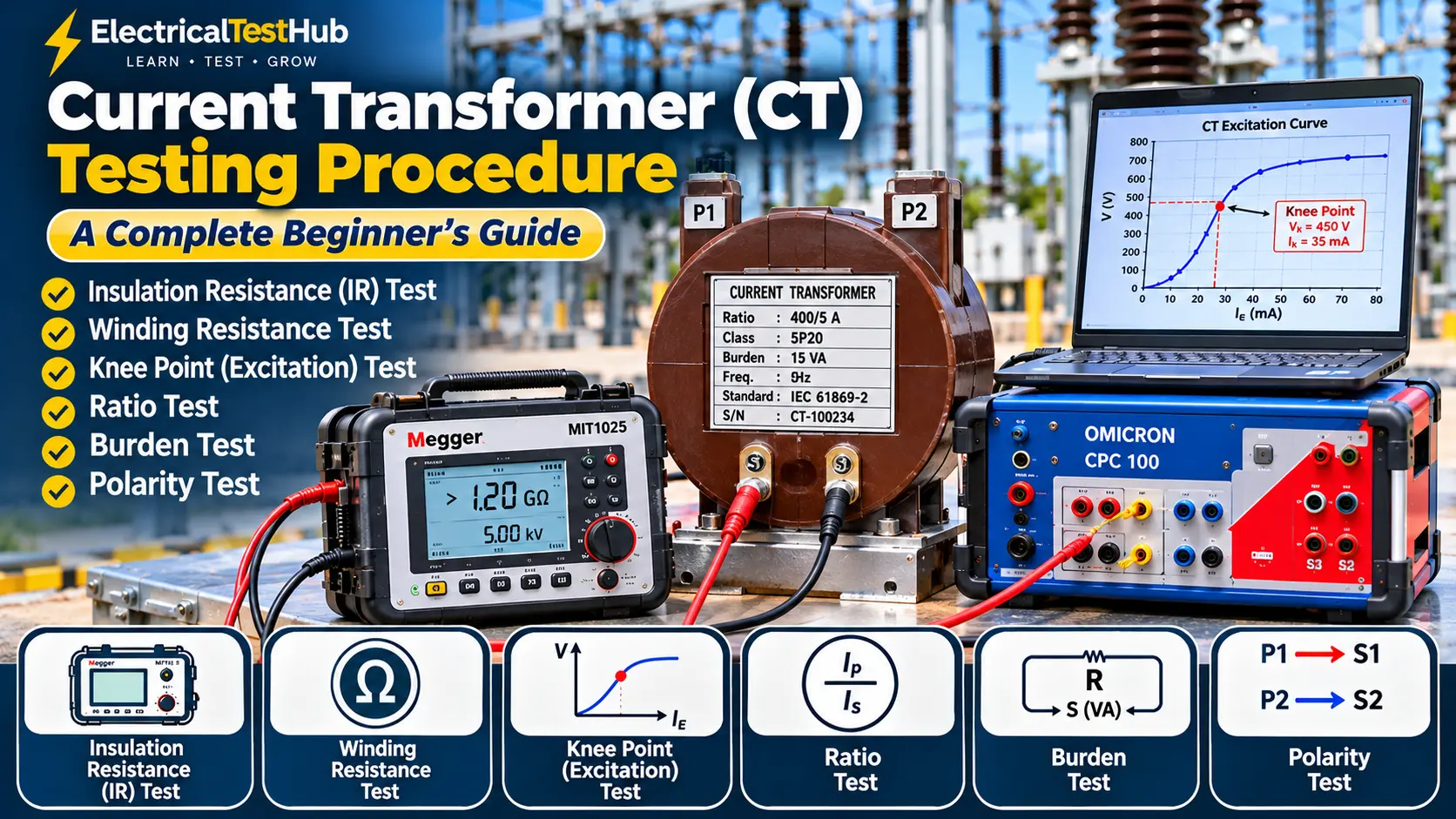
Introduction
A Current Transformer (CT) is an important instrument transformer used in electrical power systems. It reduces high primary current to a smaller, standardized secondary current so that electrical meters, measuring instruments and protection relays can safely measure and monitor the system.
For example, a CT with a ratio of 400/5 A converts a primary current of 400 A into a secondary current of approximately 5 A under its rated operating conditions.
CTs are commonly installed in:
- Electrical substations
- Power transformers
- Switchgear panels
- Protection and metering panels
- Generator protection systems
But how do we confirm that a CT is working correctly?
This is where Current Transformer Testing becomes important.
CT testing helps engineers verify the insulation condition, winding resistance, transformation ratio, polarity, excitation characteristics and connected secondary burden.
In this beginner-friendly guide, we will explain six important CT tests:
- Insulation Resistance (IR) Test
- Winding Resistance Test
- Knee Point Voltage and Excitation Current Test
- CT Ratio Test
- CT Burden Test
- CT Polarity Test
We will also explain the required instruments, basic connection diagrams, testing procedures and result interpretation.
1. Understanding Current Transformer Nameplate Details
Before starting any CT test, the first step is to check the CT nameplate.
The nameplate provides important information about the CT’s design and application.
<IMAGE PLACEHOLDER: Insert a clear photograph of an actual current transformer nameplate showing ratio, accuracy class, burden, frequency and insulation level.>
Example CT Nameplate
| Parameter | Example |
|---|---|
| CT Ratio | 400/5 A |
| Primary Current | 400 A |
| Secondary Current | 5 A |
| Accuracy Class | 5P20 |
| Rated Burden | 15 VA |
| Frequency | 50 Hz |
| Rated Voltage | 12 kV |
| Core | Protection Core |
| Standard | IEC 61869-2 |
Let’s understand these details.
CT Ratio: Indicates the relationship between primary and secondary current. For example, 400/5 A means 400 A primary corresponds to 5 A secondary.
Accuracy Class: Indicates the CT’s accuracy or protection performance under specified operating conditions.
Rated Burden: The maximum specified load connected to the CT secondary for its rated performance.
5P20: A protection CT designation. It indicates a protection class with a composite error limit of 5% at its specified accuracy limit factor of 20, under the applicable standard conditions.
Core: A CT may have separate cores for metering and protection.
Understanding CT Core Applications
| CT Core | Typical Application |
|---|---|
| Metering Core | Ammeter, energy meter and measurement |
| Protection Core | Overcurrent and earth-fault protection |
| Differential Core | Transformer or busbar differential protection |
| Special Protection Core | Special protection schemes requiring specified excitation characteristics |
A single CT may have multiple secondary cores, and each core must be identified and tested according to its purpose.
2. Current Transformer Testing Equipment
Different instruments are used for different CT tests.
| Testing Equipment | Application |
|---|---|
| Insulation Resistance Tester | CT IR test |
| Micro-Ohmmeter | CT winding resistance |
| CT Analyzer | Ratio, polarity, excitation and other CT parameters |
| OMICRON CPC 100 | CT ratio, polarity, excitation and burden-related tests |
| Secondary Injection Test Set | CT secondary circuit checks |
| Primary Injection Test Set | Ratio and complete circuit verification |
| Digital Multimeter | Supporting electrical measurements |
Popular CT Testing Equipment
OMICRON CPC 100: A multifunctional test system used for several electrical tests, including CT ratio, polarity, excitation and winding resistance with suitable test configurations.
Official reference: https://www.omicronenergy.com/en/products/cpc-100/
OMICRON CT Analyzer: A dedicated instrument for comprehensive current transformer analysis.
Official reference: https://www.omicronenergy.com/
Megger MIT1025: An insulation resistance tester suitable for appropriate insulation testing applications.
Official reference: https://www.megger.com/
DV Power: Provides current transformer testing solutions and winding resistance test equipment.
Official reference: https://www.dv-power.com/
The correct equipment depends on CT ratings, test requirements, available accessories and the manufacturer’s instructions.
3. Step-by-Step Current Transformer Testing Procedure
Test 1: Current Transformer Insulation Resistance (IR) Test
What is the IR Test?
The Insulation Resistance test checks the insulation condition between the CT secondary winding and earth.
It helps identify possible insulation problems such as:
- Moisture
- Contamination
- Insulation deterioration
- Damaged secondary wiring
- Insulation leakage to earth
Required Equipment
- Insulation Resistance Tester
- Suitable test leads
- Discharge and earthing equipment
- Digital multimeter, if required for supporting checks
Basic IR Test Connection
For a CT with secondary terminals S1 and S2:
        CT SECONDARY IR TEST

           S1 -----------+
                         |
                      CT CORE
                         |
           S2 -----------+

        Megger (+) → S1 and S2
        Megger (-) → Earth / CT body

        Test: Secondary winding to Earth
This is a simplified conceptual diagram. Connect the secondary terminals and earth points according to the approved test procedure and CT design.
Step-by-Step IR Testing Procedure
Step 1: Identify the CT
Check the CT nameplate, ratio, core number and secondary terminal markings.
Step 2: Isolate the CT
Ensure the CT is safely isolated from all possible primary current sources.
Step 3: Check the secondary circuit
Disconnect sensitive equipment such as protection relays, meters and electronic devices from the test circuit where required.
Step 4: Verify the test connection
Ensure that the secondary circuit is arranged according to the approved IR test procedure.
Step 5: Select the test voltage
Select the DC test voltage according to the CT manufacturer’s recommendation and applicable procedure. A 500 V DC test is commonly used for suitable CT secondary insulation circuits, but it is not a universal requirement.
Step 6: Apply the test voltage
Apply the test voltage for the specified duration and record the insulation resistance value.
Step 7: Complete the measurement
Record the result in MΩ or GΩ.
Step 8: Discharge the CT
After testing, discharge and earth the tested circuit using the instrument manufacturer’s procedure.
Example IR Test Result
| CT Core | Test Voltage | IR Value |
|---|---|---|
| Core 1 | 500 V DC | 2500 MΩ |
| Core 2 | 500 V DC | 1800 MΩ |
| Core 3 | 500 V DC | 3200 MΩ |
These values are illustrative only, not universal acceptance limits.
How to Evaluate IR Results?
Consider:
- Previous test readings
- Factory test results
- CT insulation design
- Environmental conditions
- Test connections
- Manufacturer’s recommendations
Important: Do not apply an insulation resistance test voltage to connected relays, meters or electronic devices unless they are specifically rated for it.
Test 2: Current Transformer Winding Resistance Test
What is Winding Resistance Testing?
The winding resistance test measures the DC resistance of the CT secondary winding.
This test helps identify:
- Loose internal connections
- Poor terminal connections
- Damaged winding conductors
- Abnormal resistance differences between CT cores
- Certain winding defects
Required Equipment
- Winding Resistance Tester
- Micro-Ohmmeter
- Four-wire Kelvin test leads
Why is a Four-Wire Connection Used?
CT secondary winding resistance can be relatively low.
If a normal two-wire measurement is used, the resistance of test leads and contact points can affect the measurement.
A four-wire Kelvin connection helps reduce this error and provides a more accurate low-resistance measurement.
Basic Connection Diagram
        CT WINDING RESISTANCE TEST

             S1
              |
              |------ Current Lead (+)
              |
            [ CT ]
              |
              |------ Current Lead (-)
              |
             S2

       Sense (+) → Near S1
       Sense (-) → Near S2
The actual connections must follow the instrument manufacturer’s four-wire connection diagram.
Step-by-Step Winding Resistance Procedure
Step 1: Ensure the CT is isolated and safe for testing.
Step 2: Identify the secondary winding terminals S1 and S2.
Step 3: Disconnect the CT secondary circuit from relays and meters as required.
Step 4: Connect the winding resistance tester to S1 and S2.
Step 5: Select a suitable test current according to the instrument and CT manufacturer’s instructions.
Step 6: Start the test and allow the reading to stabilize.
Step 7: Record the measured resistance.
Step 8: Repeat the measurement for all CT cores.
Step 9: Safely discharge the winding before disconnecting the instrument.
Example Winding Resistance Result
| CT Core | Measured Resistance |
|---|---|
| Core 1 | 0.82 Ω |
| Core 2 | 0.85 Ω |
| Core 3 | 0.81 Ω |
These are illustrative values.
How to Evaluate Winding Resistance?
Compare the readings between similar cores and with previous or factory test results.
A significant difference may indicate:
- Poor connection
- Loose terminal
- Damaged winding
- Different winding design or conductor length
Temperature must also be considered when comparing measurements.
For copper winding resistance, a commonly used temperature correction formula is:
[
R_2=R_1\times\frac{234.5+T_2}{234.5+T_1}
]
Where:
- R1 = Measured resistance
- R2 = Corrected resistance
- T1 = Temperature during measurement
- T2 = Reference temperature
Use the appropriate correction method and reference temperature specified for the CT.
Test 3: Knee Point Voltage and Excitation Current Test
This is one of the most important tests for protection-class current transformers.
What is Knee Point Voltage?
A CT has a magnetic core that carries magnetic flux when current flows through its winding.
As the secondary voltage increases, the magnetic flux also increases.
At a certain point, the core begins to saturate. Beyond this region, a relatively small increase in voltage can cause a much larger increase in excitation current.
The voltage associated with this transition is called the Knee Point Voltage (Vk), according to the relevant definition used.
Why is Knee Point Testing Important?
The test helps engineers evaluate:
- CT magnetic core characteristics
- Excitation behaviour
- Protection core suitability
- Possible shorted turns
- Differences between similar CT cores
- CT saturation characteristics
It is particularly important for protection CTs such as PX or PS classes, where specified knee-point and excitation characteristics are relevant.
What is Excitation Current?
Excitation current is the current required to magnetize the CT core when a voltage is applied to the secondary winding with the primary open-circuited.
As the applied voltage increases, the excitation current generally increases.
The relationship between applied secondary voltage and excitation current is called the Excitation Curve or Magnetization Curve.
Understanding the Excitation Curve
The curve generally has three important regions:
- Initial Region: The excitation current increases gradually as voltage increases.
- Knee Region: The curve begins to bend, indicating the transition towards saturation.
- Saturation Region: A small voltage increase causes a much larger increase in excitation current.
Knee Point Definition: Important Difference
The knee-point definition depends on the applicable standard.
- Under the IEC definition in IEC 61869-2, the knee point is associated with a 10% increase in voltage producing a 50% increase in excitation current.
- IEEE C57.13 uses a different definition based on the 45-degree tangent to the excitation curve plotted on logarithmic scales.
Therefore, an IEC knee-point value and an IEEE knee-point value may not be identical for the same CT.
Always mention the applicable definition in the test report.
Required Equipment
- CT Analyzer
- OMICRON CPC 100 with suitable configuration
- CT excitation test set
- Suitable test leads
Basic Knee Point Test Connection
        KNEE POINT / EXCITATION TEST

             CT PRIMARY
                 |
          OPEN / ISOLATED
                 |
                 X

          CT SECONDARY

             S1 --------+
                        |
                  TEST SET
                 AC VOLTAGE
                        |
             S2 --------+

       Measure:
       1. Applied Secondary Voltage
       2. Excitation Current
       3. Excitation Curve
       4. Knee Point Voltage
The CT primary must be open-circuited and safely isolated as required by the test procedure. Never allow a closed primary loop or an unintended external current path during excitation testing.
Step-by-Step Knee Point Testing Procedure
Step 1: Identify the protection CT core and check the nameplate details.
Step 2: Ensure that the CT primary is isolated and open according to the approved procedure.
Step 3: Disconnect the secondary circuit from the protection relay and other connected equipment as required.
Step 4: Connect the CT Analyzer or excitation test equipment to S1 and S2.
Step 5: Select the correct CT test mode and applicable IEC or IEEE standard definition.
Step 6: Start the excitation test.
Step 7: The instrument applies increasing AC voltage to the CT secondary winding.
Step 8: Record the applied voltage and corresponding excitation current.
Step 9: The instrument generates the excitation curve and determines the knee-point voltage and current according to the selected definition.
Step 10: After completing the test, demagnetize the CT core using the instrument’s demagnetization function or approved procedure.
Example Knee Point Test Result
| Parameter | Measured Value |
|---|---|
| Knee Point Voltage | 450 V |
| Knee Point Current | 35 mA |
| Test Frequency | 50 Hz |
| CT Core | Protection Core |
These values are illustrative only.
How to Evaluate Knee Point Results?
Compare the measured knee-point voltage and excitation current with:
- CT nameplate or guaranteed data
- Factory test report
- Applicable accuracy class requirements
- Previous test results
- Manufacturer’s recommendations
A higher knee-point voltage is not automatically better. The measured value must match the CT’s intended design and protection requirements.
Important: Always demagnetize the CT after excitation testing. Residual magnetism can affect subsequent measurements and CT performance.
Test 4: Current Transformer Ratio Test
What is a CT Ratio Test?
The ratio test verifies the relationship between primary current and secondary current.
For example, a CT with a ratio of 400/5 A should produce approximately 5 A secondary current when 400 A flows through its primary under the specified conditions.
CT Ratio Formula
[
CT\ Ratio=\frac{Primary\ Current}{Secondary\ Current}
]
Example Calculation
Suppose:
- Primary current = 400 A
- Secondary current = 5 A
[
CT\ Ratio=\frac{400}{5}=80
]
Therefore, the CT ratio is 80:1, or 400/5 A.
Required Equipment
- CT Analyzer
- OMICRON CPC 100
- Primary Injection Test Set
- Suitable current measuring instrument
Common CT Ratio Testing Methods
There are two commonly used approaches.
Method 1: Primary Injection
A known current is injected through the CT primary conductor, and the secondary current is measured.
Method 2: CT Analyzer / Voltage-Based Ratio Measurement
A dedicated CT test instrument uses a controlled test signal and measures the ratio based on the CT winding characteristics.
The selected method must be suitable for the CT design and test objective.
Basic Primary Injection Connection
         PRIMARY INJECTION TEST

       Injection Set (+)
              |
              |
          P1 [ CT ] P2
              |
              |
       Injection Set (-)

          CT SECONDARY

             S1 ---- Ammeter ---- S2

      Measure Primary Current
      Measure Secondary Current
Step-by-Step Ratio Test Procedure
Step 1: Check the CT nameplate ratio.
Step 2: Isolate the CT and make the test area safe.
Step 3: Connect the primary injection equipment to the CT primary circuit, or connect a dedicated CT Analyzer as instructed.
Step 4: Connect the secondary measuring circuit correctly.
Step 5: Apply the required test current or test signal.
Step 6: Record the primary and secondary measurements.
Step 7: Calculate the measured ratio.
Step 8: Compare the measured ratio with the nameplate ratio.
Step 9: Repeat for each core and applicable ratio tap.
Example Ratio Test Result
| CT Core | Nameplate Ratio | Measured Ratio |
|---|---|---|
| Core 1 | 400/5 A | 80.0 |
| Core 2 | 400/5 A | 80.1 |
| Core 3 | 400/5 A | 79.9 |
These are illustrative values.
Ratio Error Calculation
For ratio comparison, one common expression is:
[
Ratio\ Error(%)=
\frac{K_n-K_a}{K_a}\times100
]
Where:
- Kn = Nominal transformation ratio
- Ka = Actual transformation ratio
Use the correct convention and calculation method specified by the applicable standard or test instrument.
Important: A ratio test using a low-voltage CT Analyzer is not necessarily equivalent to a full rated-current accuracy test. For accuracy-class verification, the specified current, burden, frequency and applicable standard requirements must be considered.
Test 5: CT Burden Test
What is CT Burden?
CT burden means the total load connected to the CT secondary winding.
This load includes:
- Protection relay input
- Ammeter or energy meter
- Secondary cables
- Terminal blocks
- Test switches
- Other connected devices
The burden is normally expressed in Volt-Amperes (VA) at the rated secondary current.
Why is CT Burden Testing Important?
If the connected burden is higher than the CT’s rated burden, it may affect the CT’s accuracy and protection performance.
Excessive burden can contribute to increased secondary voltage requirements and may cause a protection CT to reach saturation earlier than expected.
CT Burden Formula
For a predominantly resistive burden:
[
VA=I_s^2\times R
]
Where:
- VA = Burden in Volt-Amperes
- Is = Rated secondary current
- R = Total secondary circuit resistance
More generally:
[
VA=I_s\times V_s
]
Where Vs is the measured voltage magnitude across the burden at the specified current.
Example Calculation
Suppose:
- CT secondary rated current = 5 A
- Total secondary circuit resistance = 0.4 Ω
Then:
[
VA=5^2\times0.4
]
[
VA=25\times0.4
]
Burden = 10 VA
If the CT nameplate rated burden is 15 VA, the calculated resistive burden is 10 VA, which is below the rated value.
This simple calculation assumes a resistive load and the stated rated current. Actual burden evaluation should account for the applicable measurement method, circuit impedance and instrument accuracy.
Step-by-Step Burden Testing Procedure
Step 1: Identify the CT secondary circuit and its rated current.
Step 2: Isolate the CT secondary from the CT winding using the approved test arrangement.
Step 3: Connect a suitable burden test instrument to the secondary circuit.
Step 4: Apply the specified test current, preferably at or near the rated secondary current when the method requires it.
Step 5: Measure the voltage and current or directly measure the circuit impedance.
Step 6: Calculate or record the burden in VA.
Step 7: Compare the measured burden with the CT nameplate rating and project requirements.
Step 8: Restore the secondary circuit and verify all connections.
Example Burden Test Result
| Parameter | Value |
|---|---|
| CT Rated Current | 5 A |
| CT Rated Burden | 15 VA |
| Measured Circuit Resistance | 0.40 Ω |
| Calculated Burden | 10 VA |
These are illustrative values.
Important: Burden testing must be performed using a suitable test arrangement. Never open an energized CT secondary circuit. Isolate the CT or use an approved method that keeps the CT secondary safely short-circuited.
Test 6: CT Polarity Test
What is CT Polarity?
CT polarity indicates the relative direction of current flow through the primary and secondary windings.
Correct polarity is important for:
- Differential protection
- Directional overcurrent protection
- Metering
- Earth-fault protection
- Parallel measurement circuits
If CT polarity is incorrect, protection relays may receive incorrect current direction information.
Understanding CT Polarity Markings
Common CT terminal markings include:
| Primary Terminals | Secondary Terminals |
|---|---|
| P1 | S1 |
| P2 | S2 |
The corresponding polarity markings indicate the relative instantaneous direction of current.
Basic DC Polarity Test Connection
          CT POLARITY TEST

             P1
              |
          +---CT---+
              |
             P2

       Battery (+) ---- Switch ---- P1

       Battery (-) ------------ P2

       Analog Meter (+) ------- S1
       Analog Meter (-) ------- S2
This is a simplified conceptual diagram. The actual DC kick test requires the approved momentary switching and meter arrangement.
Step-by-Step DC Polarity Test
Step 1: Ensure that the CT primary is isolated and safe for testing.
Step 2: Identify the primary terminals P1 and P2.
Step 3: Identify the secondary terminals S1 and S2.
Step 4: Connect a low-voltage DC battery and momentary switch to the primary winding according to the approved test arrangement.
Step 5: Connect a suitable center-zero analog meter or polarity test instrument to the secondary terminals.
Step 6: Momentarily close the switch.
Step 7: Observe the direction of the meter deflection.
Step 8: Open the switch and observe the reverse deflection.
Step 9: Compare the deflection pattern with the expected polarity arrangement.
What Does the Meter Indicate?
When the primary current is switched on, the secondary meter gives a momentary kick.
When the primary current is interrupted, the meter gives a kick in the opposite direction.
The expected direction depends on the test connection and terminal markings. Follow the instrument or manufacturer connection diagram rather than assuming that every meter deflection will be identical.
Why is Correct Polarity Important?
Suppose two CTs are connected to a differential protection relay.
If one CT has reversed polarity, the relay may detect an incorrect differential current even under normal load conditions.
This can cause unwanted relay operation.
Therefore, polarity must be verified during commissioning.
4. Understanding the Difference Between the Six CT Tests
| Test | Main Purpose | What Does It Verify? |
|---|---|---|
| Insulation Resistance | Check insulation condition | Secondary winding insulation to earth |
| Winding Resistance | Measure DC resistance | Winding and connection condition |
| Knee Point Test | Evaluate core excitation | Saturation characteristics |
| Ratio Test | Verify transformation ratio | Primary-to-secondary current relationship |
| Burden Test | Measure secondary load | Total connected secondary burden |
| Polarity Test | Verify terminal polarity | Correct current direction and phase relationship |
Each test provides different information. Passing one test does not prove that all other CT characteristics are satisfactory.
5. Recommended CT Testing Sequence
A practical commissioning sequence may be arranged as follows:
- Visual and mechanical inspection
- Nameplate verification
- Secondary wiring and terminal identification
- Insulation resistance test
- Winding resistance test
- Ratio test
- Polarity test
- Knee point / excitation test
- Demagnetization
- Burden test
- Secondary circuit verification
- Primary injection and protection circuit checks, where specified
- Final restoration and documentation
The exact sequence may vary depending on the instrument, CT design and approved test procedure. Some instruments combine multiple tests in one setup.
Important: Demagnetize the CT after excitation testing and before returning it to service. Confirm that all secondary circuits, links, shorting arrangements and single-point earth connections are restored correctly.
6. Important Safety Precautions During CT Testing
Current transformer testing requires special attention to safety.
The most important CT safety rule: Never open-circuit the secondary of an energized current transformer.
When primary current flows through a CT with an open secondary circuit, a dangerously high voltage can develop across the secondary terminals.
This can cause electric shock, insulation failure and equipment damage.
Always follow these precautions:
- Isolate the CT primary before testing.
- Apply Lockout/Tagout (LOTO).
- Verify the absence of primary current and voltage as required.
- Short the CT secondary before disconnecting connected relays or meters when the approved procedure requires it.
- Never leave an energized CT secondary open.
- Use properly rated and calibrated test instruments.
- Verify test lead connections before applying test voltage or current.
- Disconnect sensitive electronic equipment before insulation testing where required.
- Discharge the CT after applicable tests.
- Demagnetize the CT after excitation testing.
- Maintain the CT secondary single-point earthing arrangement according to the approved design.
- Restore all shorting links, test switches and earthing connections before returning the CT to service.
Only qualified and authorized personnel should perform these tests.
7. Applicable Standards for Current Transformer Testing
The following standards are important references for CT design, performance and testing.
| Standard | Application |
|---|---|
| IEC 61869-1 | General requirements for instrument transformers |
| IEC 61869-2 | Additional requirements for current transformers |
| IEEE C57.13 | Requirements for instrument transformers |
| IEEE C57.13.1 | Guide for field testing of relaying current transformers |
| IEC 60255 Series | Measuring relays and protection equipment, where applicable |
Important: The applicable standard depends on the CT type, accuracy class, test purpose and project specification. Not every field test or acceptance limit is defined by the same standard.
For formal commissioning reports, identify the exact standard edition and relevant clause used.
Official references:
- IEC Webstore: https://webstore.iec.ch/
- IEEE Standards: https://standards.ieee.org/
- OMICRON CT testing information: https://www.omicronenergy.com/en/products/cmc-ct-check/
- OMICRON CT testing guide: https://www.omicronenergy.com/download/document/F93C63B9-C972-42C3-B4E4-B60431DC865E/
8. CT Testing Report: What Should Be Included?
After completing CT testing, the engineer should prepare a professional test report.
General Information
- Client Name
- Project Name
- Substation Name
- CT Location
- CT Manufacturer
- CT Serial Number
- CT Ratio
- Rated Burden
- Accuracy Class
- Core Number
- Date of Testing
Test Result Information
| Test Name | Important Information to Record |
|---|---|
| IR Test | Test voltage, duration and measured resistance |
| Winding Resistance | Test current, winding resistance and temperature |
| Knee Point Test | Knee-point voltage, knee-point current, frequency and standard definition |
| Ratio Test | Nameplate ratio, measured ratio and ratio error |
| Burden Test | Test current, measured impedance and burden in VA |
| Polarity Test | Test method and polarity result |
Example Professional Observation
Test: CT Ratio Test
Observation: The measured transformation ratio was recorded for the respective CT core and compared with the nameplate ratio. The measured results should be evaluated against the applicable accuracy requirements and approved project criteria.
Avoid writing only “OK” or “Satisfactory” without recording the actual test results.
9. Frequently Asked Questions (FAQ)
1. What is the purpose of CT testing?
CT testing verifies the insulation, winding resistance, transformation ratio, polarity, excitation characteristics and secondary burden of a current transformer.
2. Why is the knee point voltage test important?
The knee point test evaluates the magnetic excitation characteristics of the CT core. It is especially important for protection CTs with specified knee-point requirements.
3. What is the difference between knee point voltage and excitation current?
Knee point voltage is the secondary voltage at the defined transition point of the excitation curve. Excitation current is the magnetizing current required by the CT at that voltage.
4. Why is CT demagnetization required?
Excitation testing can leave residual magnetism in the CT core. Demagnetization helps return the core to a defined magnetic state and supports reliable subsequent measurements and operation.
5. Can a CT ratio test be performed without primary injection?
Yes. A suitable CT Analyzer or voltage-based CT testing system can measure the ratio without injecting high current through the primary conductor. However, the method and its accuracy must suit the test objective.
6. What is CT burden in simple language?
CT burden is the total electrical load connected to the CT secondary winding, including relays, meters, terminals and secondary cables. It is normally expressed in VA.
7. Why is CT polarity important?
Correct polarity ensures that the secondary current has the proper relationship to the primary current. It is particularly important for differential and directional protection schemes.
8. What happens if a CT secondary is left open?
If primary current is flowing, a dangerous voltage may develop across the open secondary terminals. It can create serious safety hazards and damage the CT.
9. Which instrument is used for CT testing?
Common instruments include OMICRON CPC 100, OMICRON CT Analyzer, Megger CT testing systems, insulation resistance testers and suitable micro-ohmmeters.
10. Should every CT undergo a knee point test?
Not necessarily. The required tests depend on the CT class and application. Knee-point verification is particularly relevant to CTs with specified PX/PS-type excitation characteristics and other protection applications where required by the design.
Conclusion
Current Transformer testing is an essential part of substation commissioning and electrical maintenance.
For a new engineer, the most important thing is to understand why each test is performed.
- IR Test: Checks insulation condition.
- Winding Resistance Test: Measures secondary winding resistance.
- Knee Point Test: Evaluates magnetic core excitation and saturation characteristics.
- Ratio Test: Verifies the transformation ratio.
- Burden Test: Checks the connected secondary load.
- Polarity Test: Verifies the correct relationship between primary and secondary current directions.
A good CT testing engineer should not simply operate the test instrument and record readings. They should understand the CT nameplate, test connections, instrument settings, measured values and applicable acceptance criteria.
Always follow the manufacturer’s recommendations, relevant IEC or IEEE standards and approved site safety procedures.
Disclaimer: This article is for educational purposes. Actual CT testing must be performed by qualified personnel using approved procedures and appropriately rated test equipment.
