

Introduction
A transformer is one of the most important electrical equipment in a power system. It transfers electrical energy from one voltage level to another through electromagnetic induction.
Transformers are widely used in power plants, substations, factories, commercial buildings and electrical distribution systems.
For example, a distribution transformer may step down 11 kV voltage to 400/230 V so that electrical energy can be supplied to buildings and industrial loads.
But how do we know that a transformer is safe and ready for operation?
This is where transformer testing becomes important.
Transformer testing is the process of checking the electrical, mechanical and insulation condition of a transformer. It helps engineers identify possible defects, verify the manufacturer’s specifications and ensure that the transformer is suitable for energization.
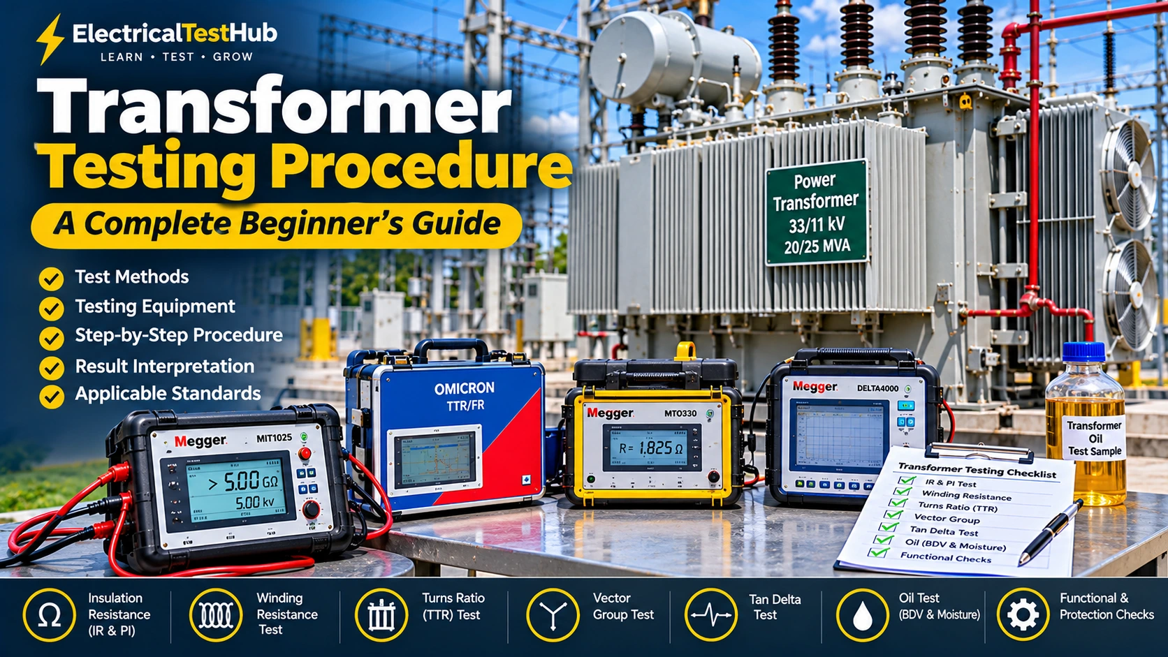
In this beginner-friendly guide, we will explain the complete transformer testing procedure, including:
- Visual and mechanical inspection
- Insulation Resistance (IR) test
- Polarization Index (PI) test
- Winding Resistance test
- Transformer Turns Ratio (TTR) test
- Vector Group test
- Magnetic Balance test
- Tan Delta test
- Transformer oil testing
- Functional and protection checks
- Final pre-commissioning inspection
Let’s understand each test step by step.
1. What Is Transformer Testing?
Transformer testing means performing different electrical and mechanical tests to evaluate the condition and performance of a transformer.
These tests help us understand whether:
- Transformer insulation is in good condition.
- Transformer windings have the correct resistance.
- The voltage transformation ratio is correct.
- The winding connections and vector group are correct.
- The insulation system is healthy.
- Transformer oil has suitable insulating properties.
- Cooling and protection systems operate correctly.
Transformer testing is generally performed during three major activities:
1.1 Factory Testing
Factory testing is performed by the transformer manufacturer before delivering the transformer.
The purpose is to verify that the manufactured transformer meets the applicable design, contractual and standard requirements.
Examples include:
- Winding resistance test
- Turns ratio test
- Vector group verification
- Impedance voltage test
- Load loss test
- No-load loss test
- Applied voltage test
- Induced voltage test
1.2 Site Acceptance Testing
After transportation and installation, the transformer is tested at the site before energization.
The purpose is to identify any damage or changes that may have occurred during transportation, installation or assembly.
Examples include:
- Insulation resistance test
- Winding resistance test
- Turns ratio test
- Tan delta test
- Oil BDV and moisture testing, where specified
- Functional checks of accessories
- Protection system verification
1.3 Preventive Maintenance Testing
Preventive maintenance testing is performed on transformers already in service.
The purpose is to monitor the transformer’s condition and identify developing problems before they cause a failure.
Examples include:
- Oil testing
- Insulation resistance testing, where appropriate
- Tan delta testing
- Winding resistance testing
- Thermography
- Dissolved Gas Analysis (DGA)
- SFRA, when required
Important: The tests required for every transformer are not identical. They depend on transformer voltage, capacity, design, insulation type, age, manufacturer recommendations and project specifications.
2. Understanding Transformer Nameplate Details
Before performing any transformer test, the first thing an engineer should do is check the transformer nameplate.
The nameplate contains important information about the transformer.
Example Transformer Nameplate
| Parameter | Example |
|---|---|
| Transformer Capacity | 1000 kVA |
| Primary Voltage | 11 kV |
| Secondary Voltage | 0.415 kV |
| Frequency | 50 Hz |
| Phase | 3 Phase |
| Vector Group | Dyn11 |
| Impedance | 6% |
| Cooling Type | ONAN |
| Tap Changer | Off-Circuit Tap Changer |
| Insulation | Oil Immersed |
Let’s understand some important details.
Transformer Capacity: Indicates the rated apparent power of the transformer. In this example, it is 1000 kVA.
Primary Voltage: The voltage supplied to the input winding. Here it is 11 kV.
Secondary Voltage: The output voltage. Here it is 415 V.
Vector Group: Indicates the winding connection and phase displacement between primary and secondary voltages.
Impedance (%Z): Indicates the percentage impedance of the transformer. It is important for fault current calculations and parallel operation.
Cooling Type: ONAN means Oil Natural Air Natural cooling.
Always record the nameplate information before starting the testing process.
3. Transformer Testing Equipment
Different instruments are required for different transformer tests.
Common transformer testing instruments include:
| Testing Equipment | Application |
|---|---|
| Insulation Resistance Tester (Megger) | IR and PI test |
| Transformer Turns Ratio Tester | TTR and vector group test |
| Winding Resistance Tester | DC winding resistance measurement |
| Tan Delta Test Set | Insulation power factor and capacitance |
| Oil BDV Test Kit | Transformer oil dielectric strength |
| Moisture-in-Oil Tester | Water content measurement |
| SFRA Analyzer | Mechanical condition assessment |
| Multimeter | General electrical measurements |
| Clamp Meter | Current measurement |
| Thermal Camera | Hotspot detection |
Popular Transformer Testing Equipment Manufacturers
- OMICRON: Transformer diagnostic and electrical testing equipment.
- Megger: Insulation resistance, winding resistance, TTR, tan delta and other transformer test equipment.
- Doble: Transformer diagnostic and insulation testing solutions.
- DV Power: Transformer winding resistance and ratio testing equipment.
Before using any instrument, check its calibration status, test lead condition, voltage/current rating and manufacturer’s instructions.
4. Step-by-Step Transformer Testing Procedure
Now let’s understand the actual transformer testing procedure.
The following sequence is a general field-testing guide. The approved project procedure and manufacturer’s recommendations must always take priority.
Test 1: Visual and Mechanical Inspection
Visual inspection is the first activity before performing electrical tests.
The objective is to identify visible damage, leakage, loose connections or abnormal conditions.
What should we check?
- Transformer tank condition.
- Oil leakage from tank, valves and gaskets.
- Oil level in the conservator tank.
- Bushing condition and cleanliness.
- Radiator and cooling fan condition.
- Silica gel breather condition.
- Temperature indicator condition.
- Buchholz relay condition.
- Pressure Relief Device (PRD).
- Earthing connections.
- Cable and busbar connections.
- Marshalling box condition.
Why is visual inspection important?
Suppose a transformer has an oil leak near the bushing gasket.
If we ignore the leakage and continue testing, the transformer may have an oil-level problem or insulation risk.
Therefore, visible abnormalities should be investigated before proceeding.
Record: Mention all visible defects, oil leakage, damaged accessories and abnormal conditions in the inspection report.
Test 2: Insulation Resistance (IR) Test
The Insulation Resistance test is one of the most common transformer tests.
Its purpose is to check the insulation resistance between:
- HV winding and Earth
- LV winding and Earth
- HV winding and LV winding
What is insulation resistance?
Insulation resistance indicates how effectively the insulation prevents unwanted current from flowing between conductors or between a conductor and earth.
A higher insulation resistance reading generally indicates better insulation condition under the test conditions, but it does not alone prove that the transformer insulation is healthy.
Required equipment
- Insulation Resistance Tester
- Suitable test leads
- Discharge/earthing equipment
- Temperature measuring instrument
Example instruments:
- Megger MIT1025
- Megger MIT1525
- Fluke 1555 Insulation Tester
IR Test Connection
For a typical two-winding transformer:
        TRANSFORMER IR TEST

          HV WINDING
          H1  H2  H3
           |   |   |
           |   |   |
        +--+---+---+
        |          |
        | TRANSFORMER
        |          |
        +--+---+---+
           |   |   |
          X1  X2  X3
          LV WINDING

      Test combinations:

      1. HV to Earth
      2. LV to Earth
      3. HV to LV
The exact connection arrangement depends on the transformer construction and test procedure. Windings and terminals that are not under test are connected or grounded as specified by the approved method.
Step-by-step IR Testing Procedure
Step 1: Isolate the transformer from all incoming and outgoing electrical sources.
Step 2: Apply the approved Lockout/Tagout (LOTO) procedure.
Step 3: Verify that the transformer is completely de-energized.
Step 4: Disconnect external connections where required by the test procedure.
Step 5: Clean and inspect the transformer terminals and bushings.
Step 6: Connect the insulation resistance tester according to the required test combination.
Step 7: Select the appropriate DC test voltage according to the transformer rating, insulation design and manufacturer’s instructions.
Step 8: Apply the test voltage for the specified duration and record the reading.
Step 9: Repeat the test for the remaining winding combinations.
Step 10: After each test, discharge and earth the winding safely using the approved procedure.
Example IR Test Result
| Test Connection | Test Voltage | IR Reading |
|---|---|---|
| HV to Earth | 5 kV DC | 2500 MΩ |
| LV to Earth | 1 kV DC | 850 MΩ |
| HV to LV | 5 kV DC | 3200 MΩ |
These are illustrative readings only, not standard acceptance limits.
How do we evaluate IR results?
Consider:
- Previous test results.
- Factory test report.
- Ambient and winding temperature.
- Humidity and surface condition.
- Transformer voltage and insulation design.
- Manufacturer recommendations.
- Applicable project acceptance criteria.
A low IR value does not automatically mean the transformer has failed. Investigate the cause before making a final decision.
Test 3: Polarization Index (PI) Test
The Polarization Index test is another insulation assessment method.
It uses two insulation resistance readings taken at different times.
PI Formula
PI = Insulation Resistance at 10 minutes / Insulation Resistance at 1 minute
Example Calculation
Suppose:
- IR at 1 minute = 1000 MΩ
- IR at 10 minutes = 1500 MΩ
Then:
PI = 1500 / 1000
PI = 1.5
What does PI indicate?
The PI ratio helps evaluate the time-dependent insulation resistance behaviour.
However, PI should not be interpreted using one universal pass/fail limit for every transformer. The result depends on insulation material, transformer design, temperature, moisture and test conditions.
Important Note
For some modern insulation systems, IR readings may be very high from the beginning and may not increase significantly with time. Therefore, a low PI ratio does not always indicate defective insulation.
Always compare PI with the manufacturer’s guidance, previous results and other diagnostic measurements.
Test 4: Transformer Winding Resistance Test
The winding resistance test measures the DC resistance of transformer windings.
It helps identify:
- Loose internal connections.
- Poor tap changer contacts.
- Damaged winding connections.
- Open circuits.
- Abnormal differences between phases.
Required Equipment
- Transformer Winding Resistance Tester
- Test cables
- Temperature measuring instrument
Example equipment:
- Megger TTRU3/TRAX winding resistance functionality, depending on configuration.
- DV Power RMO series.
- OMICRON CPC 100 with suitable accessories.
Step-by-step Winding Resistance Test
Step 1: Isolate and safely discharge the transformer.
Step 2: Identify the HV and LV terminals.
Step 3: Connect the winding resistance tester to the required winding terminals.
Step 4: Select the appropriate test current according to the winding rating and instrument instructions.
Step 5: Start the test and allow the reading to stabilize.
Step 6: Record the resistance value for each phase.
Step 7: Repeat the measurement for the required tap positions.
Step 8: After completing the test, allow the instrument to safely discharge the winding before disconnecting the leads.
Example Winding Resistance Result
| Phase | HV Resistance |
|---|---|
| R Phase | 1.825 Ω |
| Y Phase | 1.831 Ω |
| B Phase | 1.828 Ω |
These are illustrative values only.
Why is temperature important?
Winding resistance changes with temperature.
For copper winding resistance, a commonly used temperature correction relationship is:
R₂ = R₁ × (234.5 + T₂) / (234.5 + T₁)
Where:
- R₁ = Measured resistance
- R₂ = Resistance at reference temperature
- T₁ = Temperature during measurement
- T₂ = Reference temperature
For aluminium windings, the appropriate temperature constant is different.
Always use the correct conductor material and manufacturer’s correction method.
Test 5: Transformer Turns Ratio (TTR) Test
The Transformer Turns Ratio test verifies whether the ratio between primary and secondary windings is correct.
It is one of the most important transformer commissioning tests.
What is transformer turns ratio?
A transformer changes voltage according to the ratio of turns in its primary and secondary windings.
For an ideal transformer:
V₁ / V₂ = N₁ / N₂
Where:
- V₁ = Primary voltage
- V₂ = Secondary voltage
- N₁ = Primary winding turns
- N₂ = Secondary winding turns
Example Calculation
Suppose a transformer has:
- HV voltage = 11,000 V
- LV voltage = 415 V
The voltage ratio is:
11,000 / 415 = 26.51
Therefore, the nominal voltage ratio is approximately 26.51:1.
Step-by-step TTR Test Procedure
Step 1: Isolate and discharge the transformer.
Step 2: Check the nameplate voltage and vector group.
Step 3: Connect the TTR tester to the HV and LV terminals.
Step 4: Select the correct transformer configuration and vector group in the instrument.
Step 5: Enter the nameplate information.
Step 6: Start the test.
Step 7: Record the measured ratio for each phase.
Step 8: Repeat the test at every required tap position.
Step 9: Compare the measured ratio with the calculated or nameplate ratio.
Example TTR Result
| Phase | Expected Ratio | Measured Ratio |
|---|---|---|
| R Phase | 26.51 | 26.49 |
| Y Phase | 26.51 | 26.52 |
| B Phase | 26.51 | 26.50 |
These values are illustrative only.
Why is TTR testing important?
An incorrect ratio may indicate:
- Incorrect winding turns.
- Winding connection problems.
- Shorted turns.
- Tap changer defects.
- Incorrect tap position.
- Measurement or connection errors.
The acceptance tolerance must be taken from the applicable standard, manufacturer and project specification.
Test 6: Vector Group Test
The vector group identifies the winding connection and the phase displacement between the HV and LV sides.
For example:
Dyn11
This means:
- D = HV winding connected in Delta.
- y = LV winding connected in Star.
- n = Neutral point brought out.
- 11 = Clock notation indicating phase displacement.
Why is vector group testing necessary?
It verifies that the actual winding connections and phase displacement match the nameplate.
This is especially important when transformers are operated in parallel.
Example
Two transformers intended for parallel operation must have compatible voltage ratios, phase sequence, vector groups and other operating characteristics.
If their phase displacement is incompatible, circulating currents or severe faults may occur.
Testing Procedure
- Isolate the transformer.
- Check the nameplate vector group.
- Connect the TTR tester using the correct terminal arrangement.
- Select the appropriate vector group configuration.
- Run the test.
- Compare the measured phase relationship with the nameplate.
Many modern TTR instruments perform ratio and vector group verification together.
Test 7: Magnetic Balance Test
The magnetic balance test is a diagnostic test used to assess the magnetic circuit behaviour of a three-phase transformer.
It can help identify certain winding and magnetic circuit abnormalities.
Testing Principle
A low AC voltage is applied to one phase of a winding, while the induced voltages in the other phases are measured.
The test is repeated on the remaining phases.
Basic Procedure
Step 1: Isolate the transformer completely.
Step 2: Apply a suitable low AC voltage to the specified winding terminals.
Step 3: Measure the induced voltages across the other winding terminals.
Step 4: Repeat the procedure for the remaining phases.
Step 5: Compare the measured voltage pattern between phases.
Important Note
The expected magnetic balance pattern depends on the transformer core construction, winding connection and test arrangement.
Do not use one universal voltage ratio as the acceptance criterion. Interpret the result using the manufacturer’s test procedure and comparison with other phases or previous records.
Test 8: Transformer Tan Delta Test
The Tan Delta test is used to evaluate the dielectric condition of transformer insulation.
It is also called the Dissipation Factor or Power Factor test.
What is Tan Delta?
When AC voltage is applied to insulation, a small amount of energy is lost as heat.
Tan Delta measures the relationship between the resistive and capacitive components of the insulation current.
A higher dissipation factor may indicate:
- Moisture in insulation.
- Contamination.
- Insulation deterioration.
- Ageing of insulation.
- Other dielectric abnormalities.
Common Test Modes
Depending on the instrument and test arrangement, transformer insulation tests may include:
- GST
- GST-Ground
- UST
- UST-A
The selected test mode depends on the test object and required isolation of the insulation paths.
Basic Testing Procedure
- Isolate and discharge the transformer.
- Clean the bushings and test terminals.
- Connect the test set according to the required measurement mode.
- Select the correct test configuration.
- Apply the specified AC test voltage.
- Record capacitance and dissipation factor.
- Repeat for the required winding and bushing combinations.
- Compare results with previous readings and manufacturer recommendations.
Important Considerations
Tan delta results are affected by temperature, test voltage, insulation condition, moisture and test connections.
Always record the test temperature and use an appropriate temperature correction method where applicable.
There is no single universal acceptable tan delta value for all transformers.
Test 9: Transformer Oil BDV Test
[IMAGE PLACEHOLDER: Insert a real photograph of a transformer oil BDV test kit with an oil test vessel and electrodes.]
Oil-immersed transformers use insulating oil for electrical insulation and cooling.
The BDV test measures the dielectric breakdown strength of the oil sample under a specified test method.
What is BDV?
BDV stands for Breakdown Voltage.
It is the voltage at which the oil sample electrically breaks down under the specified electrode arrangement and test conditions.
A low BDV result may indicate moisture, contamination or other oil quality problems.
Required Equipment
- Oil BDV Test Kit
- Clean oil sampling bottle
- Oil sampling accessories
- Temperature and environmental recording equipment, as required
Testing Procedure
Step 1: Collect the oil sample using a clean, dry sampling bottle.
Step 2: Avoid moisture, dust and air contamination during sampling.
Step 3: Prepare the BDV test vessel according to the instrument instructions.
Step 4: Fill the vessel carefully with the oil sample.
Step 5: Select the correct electrode gap and test method.
Step 6: Start the test.
Step 7: Record the breakdown voltage for the required number of measurements.
Step 8: Calculate and report the result according to the applicable test method.
Important Note
Oil BDV results depend on the test method, electrode shape, gap, sample condition and number of breakdowns.
Do not compare results obtained using different test methods without considering these differences.
Test 10: Transformer Oil Moisture Test
The moisture content test determines the amount of water present in transformer oil.
Moisture is important because it can affect the dielectric properties of oil and the condition of cellulose insulation.
Why is moisture testing important?
Excessive moisture can:
- Reduce dielectric strength.
- Accelerate insulation ageing.
- Increase the risk of insulation failure.
- Affect the moisture balance between oil and paper insulation.
Testing Method
Water content in transformer oil is commonly measured using Karl Fischer titration.
The result is usually expressed in parts per million (ppm).
Moisture content should be interpreted with consideration of oil temperature, transformer condition, oil type and the applicable standard.
For further investigation of transformer oil condition, Dissolved Gas Analysis (DGA) may also be required.
Test 11: SFRA Test (Sweep Frequency Response Analysis)
SFRA is an advanced diagnostic test used to assess the mechanical integrity of transformer windings and core structures.
It is particularly useful after transportation, major fault events or suspected internal mechanical damage.
What can SFRA detect?
- Winding displacement.
- Core movement.
- Winding deformation.
- Certain internal connection abnormalities.
- Changes in the transformer’s mechanical structure.
How does SFRA work?
The test instrument injects a low-voltage signal over a range of frequencies and measures the transformer’s response.
The resulting frequency response curve is compared with a reference fingerprint.
Why is comparison important?
The SFRA test is mainly a comparative diagnostic method.
The engineer compares the results with:
- Previous test results from the same transformer.
- Factory reference measurements.
- Similar transformers, where appropriate.
- Phase-to-phase measurements.
IEC 60076-18 is the relevant IEC standard for transformer frequency response measurement.
Test 12: Functional and Protection System Checks
Electrical testing alone is not enough to confirm that a transformer is ready for operation.
Its accessories, cooling systems, alarms and protection devices must also be checked.
Important Functional Checks
| Equipment / Accessory | What Should Be Checked? |
|---|---|
| Buchholz Relay | Alarm and trip operation |
| Oil Temperature Indicator (OTI) | Temperature indication, alarm and trip contacts |
| Winding Temperature Indicator (WTI) | Indication, alarm and trip contacts |
| Pressure Relief Device (PRD) | Mechanical condition and alarm/trip contacts |
| Magnetic Oil Gauge (MOG) | Oil level indication and low-level alarm |
| Cooling Fans | Manual and automatic operation |
| Oil Pumps | Operation and control circuit |
| OLTC | Tap operation and position indication |
| Marshalling Box | Wiring, terminal tightness and heater |
| Transformer Protection Relay | Protection logic and trip circuit |
Why are these checks important?
Consider a transformer with healthy winding insulation but a defective cooling fan control system.
The transformer may operate normally at first, but excessive temperature can develop under higher loading conditions.
Therefore, all applicable auxiliary systems must be checked before energization.
5. Complete Transformer Testing Checklist
The following table provides a simplified overview for beginners.
| SL | Test Name | Purpose |
|---|---|---|
| 1 | Visual Inspection | Check physical condition |
| 2 | Insulation Resistance Test | Assess insulation resistance |
| 3 | Polarization Index Test | Evaluate time-dependent insulation behaviour |
| 4 | Winding Resistance Test | Measure winding DC resistance |
| 5 | Turns Ratio Test | Verify transformation ratio |
| 6 | Vector Group Test | Verify winding connection and phase displacement |
| 7 | Magnetic Balance Test | Assess magnetic circuit behaviour |
| 8 | Tan Delta Test | Assess dielectric insulation condition |
| 9 | Oil BDV Test | Measure oil dielectric breakdown strength |
| 10 | Moisture Content Test | Determine water content in oil |
| 11 | SFRA Test | Assess mechanical integrity |
| 12 | Functional Checks | Verify accessories and auxiliary systems |
| 13 | Protection Checks | Verify alarms, trip logic and protection circuits |
Not every test is mandatory for every transformer. The approved scope should be established before testing begins.
6. Transformer Testing Report: What Should Be Included?
After completing the tests, engineers should prepare a proper testing report.
A professional report should contain:
General Information
- Client Name
- Project Name
- Location
- Transformer Identification Number
- Transformer Manufacturer
- Transformer Capacity
- HV/LV Voltage
- Vector Group
- Cooling Type
- Serial Number
- Date of Testing
Test Information
- Test Name
- Testing Equipment
- Equipment Model
- Equipment Serial Number
- Calibration Details
- Test Connection
- Applied Test Voltage or Current
- Test Temperature
- Measured Values
- Acceptance Criteria and Reference
- Observations
- Final Assessment
Example Observation
Test: Insulation Resistance Test
Observation: The measured insulation resistance values were recorded for HV-Earth, LV-Earth and HV-LV combinations. The readings should be evaluated with reference to the manufacturer’s factory test report, test temperature and applicable project requirements.
This type of observation is more professional than simply writing “IR Test OK.”
7. Applicable Standards for Transformer Testing
The following standards are useful references for power transformer testing and commissioning.
| Standard | Application |
|---|---|
| IEC 60076-1 | General requirements for power transformers |
| IEC 60076-2 | Temperature rise requirements for liquid-immersed transformers |
| IEC 60076-3 | Insulation levels, dielectric tests and external clearances |
| IEC 60076-5 | Ability to withstand short circuit |
| IEC 60076-18 | Measurement of frequency response |
| IEC 60422 | Supervision and maintenance of mineral insulating oils |
| IEC 60156 | Determination of breakdown voltage of insulating liquids |
| IEC 60567 | Oil sampling and analysis of free and dissolved gases |
Official references should be checked before preparing a formal test procedure or report. The applicable edition and clauses depend on the transformer design and test scope.
8. Safety Precautions During Transformer Testing
Transformer testing involves electrical hazards and stored energy. Safety must always come before testing.
Follow these precautions:
- Obtain the required Permit to Work (PTW).
- Isolate the transformer from all electrical sources.
- Apply Lockout/Tagout (LOTO).
- Verify the absence of voltage using an appropriately rated voltage detector.
- Discharge and earth the transformer before connecting test equipment.
- Identify all connected circuits, including LV, HV, neutral and auxiliary connections.
- Use properly rated and calibrated test equipment.
- Establish a safe testing area with warning signs and barriers.
- Do not disconnect energized CT secondary circuits.
- Discharge test objects after IR, Tan Delta and other applicable tests.
- Keep unauthorized personnel away from the testing area.
- Restore all temporary connections and protection circuits according to the approved procedure.
Important: A transformer can retain electrical charge after testing. Always follow the instrument manufacturer’s discharge procedure and verify that the equipment is safe before touching the terminals.
9. Frequently Asked Questions (FAQ)
1. What is the first test of a transformer?
Visual and mechanical inspection is normally the first activity. Before electrical testing, engineers should check the transformer’s physical condition, oil level, bushings, valves, cooling system and accessories.
2. Which tests are important during transformer commissioning?
Common commissioning tests include insulation resistance, winding resistance, turns ratio, vector group, tan delta where specified, oil testing and functional checks of protection and accessories.
3. Why is the IR test performed on a transformer?
The IR test evaluates insulation resistance between windings and earth or between windings. It helps identify certain insulation problems, but it cannot independently confirm the complete health of transformer insulation.
4. What is the purpose of the TTR test?
The TTR test verifies whether the transformer voltage ratio is consistent with the nameplate and winding configuration.
5. Why is winding resistance measured?
Winding resistance measurement helps identify abnormal resistance, loose connections, winding problems and certain tap changer contact defects.
6. What is the purpose of the Tan Delta test?
Tan Delta testing assesses dielectric losses in the insulation system. It helps identify possible moisture, contamination and insulation deterioration.
7. Is transformer oil BDV testing sufficient to confirm oil quality?
No. BDV is only one part of transformer oil assessment. Depending on the application, moisture content, acidity, dissolved gases, dielectric dissipation factor and other oil tests may also be required.
8. Is every transformer required to undergo an SFRA test?
No. SFRA is an advanced diagnostic test. It may be specified during commissioning, after transportation, following a major fault or when mechanical damage is suspected.
9. How often should transformer testing be performed?
The testing interval depends on transformer criticality, loading, operating environment, manufacturer’s recommendations, condition history and the maintenance program.
10. Can a transformer be energized immediately after testing?
Only after all required tests and inspections are completed satisfactorily, temporary test connections are removed, protective earthing is restored or removed as required by the switching procedure, protection systems are returned to service and the responsible authority approves energization.
Conclusion
Transformer testing is an essential activity for ensuring the safety, reliability and performance of electrical power systems.
For beginners, it is important to understand that each test has a specific purpose.
The IR test evaluates insulation resistance, the PI test examines time-dependent insulation behaviour, the winding resistance test checks winding resistance, and the TTR test verifies the voltage transformation ratio. Other tests, such as Tan Delta, BDV, moisture content and SFRA, provide additional information about the transformer’s insulation and mechanical condition.
A good transformer testing engineer does not simply perform tests and record readings. They understand why each test is required, how to connect the instrument, how to interpret the results and how to prepare a professional testing report.
Remember: Always follow the manufacturer’s recommendations, applicable IEC standards, approved project procedures and site safety requirements.
Disclaimer: This article is intended for educational purposes. Transformer testing must be performed by qualified personnel using approved procedures and appropriately rated instruments.
