

Introduction
A disconnector switch, also known as an isolator, is an essential component of electrical substations. It provides electrical isolation so that maintenance can be performed on transformers, circuit breakers, busbars and transmission lines under an approved safety procedure.
To maintain reliable operation, electrical engineers and technicians use different testing instruments to assess contact resistance, insulation condition, mechanical operation, control circuits and interlocking systems.
Several manufacturers, including Megger, Fluke and other electrical test equipment suppliers, offer instruments suitable for different parts of disconnector testing.
In this article, we will explain the most useful disconnector switch testing tools, their applications, commonly used equipment models, testing procedures and important safety precautions.
1. Why Is Disconnector Switch Testing Important?
Disconnectors operate in demanding electrical environments. Outdoor substations may expose them to dust, moisture, corrosion, temperature variations and mechanical wear.
Without proper inspection and maintenance, these conditions can contribute to:
- High electrical contact resistance
- Contact overheating
- Damaged or contaminated insulators
- Mechanical misalignment
- Stiff operating mechanisms
- Faulty auxiliary contacts
- Incorrect position indication
- Malfunctioning motor drives or interlocks
Suitable testing equipment helps identify these problems and provides documented results for commissioning and preventive maintenance.
The required tests depend on the equipment design, manufacturer instructions, maintenance history and approved testing scope.
2. Essential Disconnector Switch Testing Equipment
2.1 Micro-ohmmeter / Contact Resistance Tester
Recommended equipment:
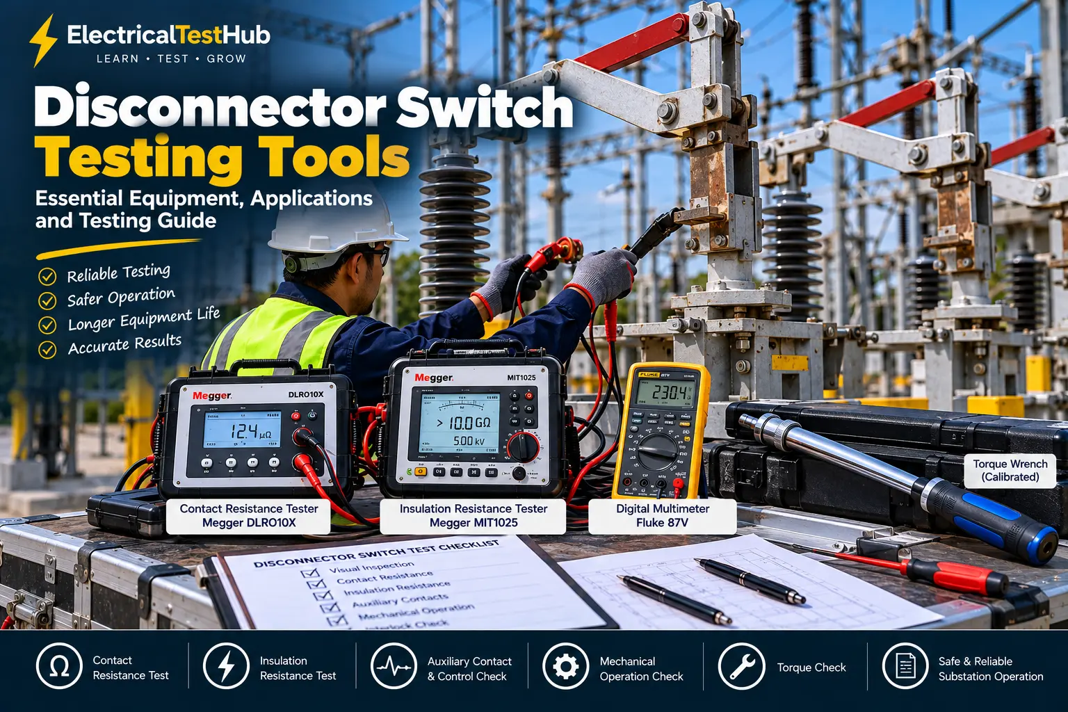
- Megger DLRO10X
- Megger DLRO200
- Other suitable low-resistance micro-ohmmeters
Main purpose: Measuring the resistance of closed disconnector main contacts.
A micro-ohmmeter is one of the most important instruments used for disconnector electrical testing. It measures very low resistance, helping engineers identify potential problems in contact assemblies and conductive connections.
The Megger DLRO10X, for example, supports low-resistance measurements with test currents up to 10 A DC. The appropriate instrument and test current must be selected according to the equipment manufacturer’s instructions.
Typical applications:
- Main contact resistance measurement
- Phase-by-phase comparison
- Assessment of specified conductive connections
- Comparison with historical test results
Basic testing procedure:
- Isolate the equipment and establish the required safety conditions.
- Close the disconnector according to the approved test procedure.
- Connect the current and potential leads to the specified measurement points.
- Select the required test current.
- Measure and record resistance for each pole.
- Compare the results with manufacturer limits and previous readings.
A four-terminal Kelvin connection helps reduce errors caused by test-lead resistance.
Official product link: Megger DLRO10X Low Resistance Ohmmeter
2.2 Insulation Resistance Tester
Recommended equipment:
- Megger MIT515/2
- Megger MIT1025/2
- Suitable Megger S1 series instruments
Main purpose: Assessing the insulation condition of electrical equipment.
An insulation resistance tester applies a specified DC test voltage and measures insulation resistance. The test can help identify insulation problems associated with moisture, contamination or deterioration.
Depending on the disconnector design and approved procedure, tests may be conducted on specified insulation paths between live parts and earth or across open contacts.
Important testing considerations:
- Select the test voltage according to the manufacturer’s procedure.
- Disconnect or protect sensitive circuits where required.
- Record the applied voltage, test duration, temperature and resistance.
- Discharge the equipment safely after testing.
- Compare the readings with applicable criteria and previous results.
Do not assume that one insulation-test voltage is suitable for every disconnector. GIS and compact switchgear may require equipment-specific procedures.
Official product link: Megger Electrical Insulation Testing Equipment
2.3 Digital Multimeter
Recommended equipment:
- Fluke 87V
- Other appropriately rated industrial digital multimeters
Main purpose: Checking auxiliary contacts, control circuits and electrical supply values.
A digital multimeter is useful when troubleshooting motor-operated disconnectors and their control panels.
Typical applications:
- Checking control supply voltage
- Verifying auxiliary contact continuity
- Troubleshooting local and remote indication
- Checking control wiring and fuses after appropriate isolation
A digital multimeter is not a replacement for a micro-ohmmeter when accurate low-resistance measurements of main contacts are required.
Official product link: Fluke 87V Industrial Multimeter
2.4 Torque Wrench
Main purpose: Tightening designated mechanical fasteners to the specified torque.
Incorrectly tightened connections can contribute to loose joints, overheating, mechanical damage or contact misalignment.
A calibrated torque wrench is useful for maintenance tasks involving specified bolts, mounting assemblies and electrical connections.
Typical applications:
- Checking designated terminal connections
- Tightening specified mounting fasteners
- Maintaining mechanical assemblies
- Supporting corrective maintenance
Always use the torque value specified by the equipment manufacturer. Excessive tightening can damage components.
2.5 Mechanical Measuring Tools
Recommended tools:
- Digital vernier caliper
- Steel measuring rule
- Feeler gauge, where specified
- Manufacturer-approved alignment gauges
Main purpose: Checking mechanical dimensions and alignment.
Mechanical measuring tools can help verify specified clearances, dimensions and contact alignment during maintenance.
For example, a technician may need to check whether the contact assembly or operating linkage matches the dimensions provided in the manufacturer’s drawings.
Do not use generic dimensions as acceptance limits. Always follow the equipment-specific documentation.
2.6 Approved Voltage Detector
<AsyncImage query=”high voltage capacitive voltage detector with insulated operating pole used by qualified substation technicians product photograph” aspectRatio=”16:9″ width=”100%” />
Main purpose: Verifying the absence of voltage as part of the approved safety procedure.
An open-position indicator does not prove that a circuit is de-energized. An appropriately rated voltage detector is required to verify the electrical safety condition.
The detector must be suitable for the system voltage and used according to the manufacturer’s instructions and site safety rules.
Important: Voltage verification, lockout/tagout, earthing and discharge arrangements must follow the authorized switching procedure.
2.7 Control Circuit and Interlock Testing Equipment
<AsyncImage query=”electrical technician testing motor operated high voltage disconnector control cabinet auxiliary relay wiring with multimeter substation maintenance” aspectRatio=”16:9″ width=”100%” />
Recommended equipment:
- Digital multimeter
- Suitable control-circuit test leads
- Manufacturer-specific diagnostic equipment, where available
Main purpose: Verifying the control and interlocking functions of motor-operated disconnectors.
These checks help confirm that the mechanism, auxiliary contacts and position indications function as intended.
Typical checks:
- Local and remote position indication
- Motor supply and control voltage
- Auxiliary contact operation
- Limit-switch operation
- Electrical and mechanical interlocking
Use the correct wiring diagrams and approved procedures. Never bypass an interlock simply to complete a test.
2.8 Inspection Camera and Reporting Tools
<AsyncImage query=”substation maintenance engineer photographing outdoor high voltage disconnector contact mechanism inspection checklist clipboard” aspectRatio=”16:9″ width=”100%” />
Recommended tools:
- Digital camera or suitable inspection camera
- Inspection light
- Maintenance checklist
- Laptop or reporting software
Main purpose: Recording equipment condition and test results.
Photographs and structured test records make it easier to compare results during future maintenance.
A professional test report should include:
- Equipment identification and nameplate details
- Test instrument make and model
- Calibration details, where required
- Test method and settings
- Phase-wise measurements
- Observations and defects
- Corrective actions and final conclusion
3. Comparison of Disconnector Switch Testing Tools
| Testing tool | Primary application | Typical result |
|---|---|---|
| Micro-ohmmeter | Main contact resistance | Resistance in µΩ or mΩ |
| Insulation resistance tester | Insulation assessment | Resistance in MΩ or GΩ |
| Digital multimeter | Auxiliary and control circuits | Voltage, resistance or continuity |
| Torque wrench | Specified fastener tightening | Applied torque |
| Mechanical measuring tools | Dimensions and alignment | Measurement against drawings |
| Voltage detector | Safety verification | Voltage presence or absence indication |
| Control-circuit equipment | Motor drive and interlock checks | Functional result |
| Camera and reporting tools | Inspection documentation | Photographs and test records |
4. How to Select the Right Testing Equipment
Before purchasing or selecting a testing instrument, consider the following factors.
Equipment voltage and design: Confirm whether the equipment is an outdoor air-insulated disconnector, part of GIS, or integrated into metal-enclosed switchgear.
Measurement requirements: Select the instrument according to the actual test. A micro-ohmmeter is suitable for low-resistance measurement, while a multimeter is generally used for control-circuit troubleshooting.
Instrument accuracy and range: Confirm the required measurement range, accuracy, resolution and suitable test leads.
Manufacturer requirements: Follow the specified test current, test voltage, connections and acceptance criteria.
Calibration: Verify the calibration status according to the project’s quality requirements.
Reporting capability: Data storage and export can be helpful when testing multiple phases or preparing commissioning reports.
5. Practical Example: Testing an 11 kV Disconnector
Consider an 11 kV outdoor disconnector installed in a distribution substation.
During a planned outage, the maintenance team may perform the following activities according to the approved test plan.
| Step | Activity | Instrument |
|---|---|---|
| 1 | Visual inspection | Inspection light and camera |
| 2 | Verify absence of voltage | Approved voltage detector |
| 3 | Inspect dimensions and alignment | Appropriate measuring tools |
| 4 | Measure main contact resistance | Micro-ohmmeter |
| 5 | Perform insulation resistance testing, if specified | Insulation resistance tester |
| 6 | Check auxiliary contacts | Digital multimeter |
| 7 | Verify motor operation and interlocks | Approved control test equipment |
| 8 | Check specified fastener torque | Calibrated torque wrench |
| 9 | Record findings | Checklist and reporting software |
Suppose the measured contact resistance of one phase is significantly higher than the other phases. The engineer should first verify the connections and repeat the measurement under comparable conditions.
The engineer can then investigate the contact assembly and operating mechanism as permitted by the manufacturer.
The final conclusion should be based on the applicable manufacturer limits, test conditions and historical data. A phase difference alone does not automatically establish failure.
6. Applicable IEC Standard
IEC 62271-102 is a key international standard for AC disconnectors and earthing switches used in indoor and outdoor installations at nominal voltages above 1,000 V. The IEC catalogue lists IEC 62271-102:2018 with Amendment 1:2022 as the consolidated publication available through its standards store. <Cite refs={[“turn303272search0″,”turn303272search2”]}/>
Official reference: IEC 62271-102 — AC Disconnectors and Earthing Switches
The standard should be consulted in the applicable edition alongside the equipment manufacturer’s instructions. It does not establish one universal field-test acceptance limit for every disconnector.
7. Safety Precautions During Disconnector Testing
Disconnector testing can involve high voltage, stored energy and moving mechanical components. Only qualified personnel should carry out testing under an approved safety procedure.
Before starting:
- Obtain the approved work permit and switching authorization.
- Identify all supply sources and possible backfeed paths.
- Isolate the equipment and secure it against reconnection.
- Apply lockout/tagout according to site requirements.
- Verify the absence of voltage using the approved method.
- Apply earthing and discharge measures as required.
- Confirm the test boundaries and isolate sensitive circuits where necessary.
- Use suitable PPE and correctly rated instruments.
- Keep personnel clear of moving mechanisms during operation tests.
- Restore the equipment only through the authorized procedure.
Never operate a conventional disconnector under load unless it is explicitly designed and rated for that switching duty.
8. Frequently Asked Questions
Which instrument is used for disconnector contact resistance testing?
A suitable micro-ohmmeter or low-resistance ohmmeter is used to measure the resistance of closed main contacts.
Can I use a multimeter for contact resistance testing?
A multimeter can check basic continuity, but it generally cannot replace a suitable micro-ohmmeter for accurate low-resistance measurements.
Which instrument is used for insulation resistance testing?
A suitable insulation resistance tester is used with the test voltage and connection arrangement specified by the manufacturer.
Is a circuit breaker timing analyzer required for disconnector testing?
Not normally for a conventional disconnector. Mechanical operation, contact alignment, position indication and interlocks are commonly checked. Specialized timing or travel measurement equipment is needed only when required by the equipment design or approved procedure.
What is the main standard for high-voltage disconnectors?
IEC 62271-102 is a key standard for AC disconnectors and earthing switches. Confirm the applicable edition and manufacturer requirements for the equipment under test.
Conclusion
Selecting the correct disconnector switch testing tools is essential for reliable substation maintenance. Common instruments include micro-ohmmeters, insulation resistance testers, digital multimeters, mechanical measuring tools, torque wrenches and approved voltage detectors.
Each instrument serves a different purpose. Correct instrument selection, safe working practices, manufacturer-approved procedures and accurate reporting help engineers identify defects and assess equipment condition.
For professional maintenance reports, document the instrument details, test settings, phase-wise readings, observations and corrective actions.
Related Articles on ElectricalTestHub
- Circuit Breaker Testing Equipment: OMICRON, Megger and DV Power
- Types of Electrical Testing: A Beginner’s Complete Overview
- Understanding Electrical Test Results
- Disconnector Switch: Working Principle, Types, Testing and Maintenance
Official External Resources
- Megger DLRO10X — Contact Resistance Testing
- Megger — Insulation Resistance Testing
- Fluke 87V — Industrial Digital Multimeter
- IEC 62271-102 — Official Standard Information
Disclaimer: This article is for educational purposes. Actual switching, testing and maintenance must be performed by qualified personnel using approved safety procedures and the equipment manufacturer’s instructions.
