

Introduction
Power cables are essential components of electrical distribution systems. They carry electrical energy between transformers, switchgear, substations, distribution panels and industrial equipment. A cable insulation failure, damaged conductor or defective termination can cause equipment damage, unexpected outages and serious safety risks.
Power cable testing tools help electrical engineers and technicians evaluate cable insulation, verify conductor continuity, identify faults and assess cable condition before energization or during maintenance.
Different tools are required for different cable types and voltage levels. For example, an insulation resistance tester may be suitable for routine checks on a low-voltage cable, while a medium-voltage cable may require a dedicated Very Low Frequency (VLF) test system or advanced diagnostic equipment.
In this guide, we will explain the most important power cable testing tools, their applications, practical examples and the standards engineers should consider.
1. What Are Power Cable Testing Tools?
Power cable testing tools are electrical instruments used to check the condition, integrity and performance of power cables. They can be used during installation, commissioning, preventive maintenance, troubleshooting and condition assessment.
Common cable testing activities include:
- Insulation resistance testing
- Conductor continuity testing
- Conductor resistance measurement
- Cable sheath integrity testing
- High-voltage withstand testing
- Cable fault location
- Cable route tracing and identification
- Tan delta and partial discharge diagnostics
The appropriate test depends on the cable’s rated voltage, insulation material, age, installation conditions and the purpose of the test.
For a beginner’s introduction, read our guide to Types of Electrical Testing.
2. Insulation Resistance Tester (Megger)
An insulation resistance tester, commonly called a Megger, is one of the most frequently used instruments for electrical cable testing.
What does an insulation resistance tester do?
It applies a selected DC test voltage and measures the resistance of the insulation between conductors or between a conductor and earth, as applicable.
The result is generally displayed in megaohms (MΩ) or gigaohms (GΩ).
A low or unstable insulation resistance reading may indicate moisture, contamination, insulation deterioration, damage or an incorrect test connection. However, the reading must be interpreted in context.
Common applications
- LV power cable insulation checks
- Checking insulation between phase conductors
- Checking conductor-to-earth insulation
- Comparing readings between phases
- Recording insulation condition during maintenance
Example equipment
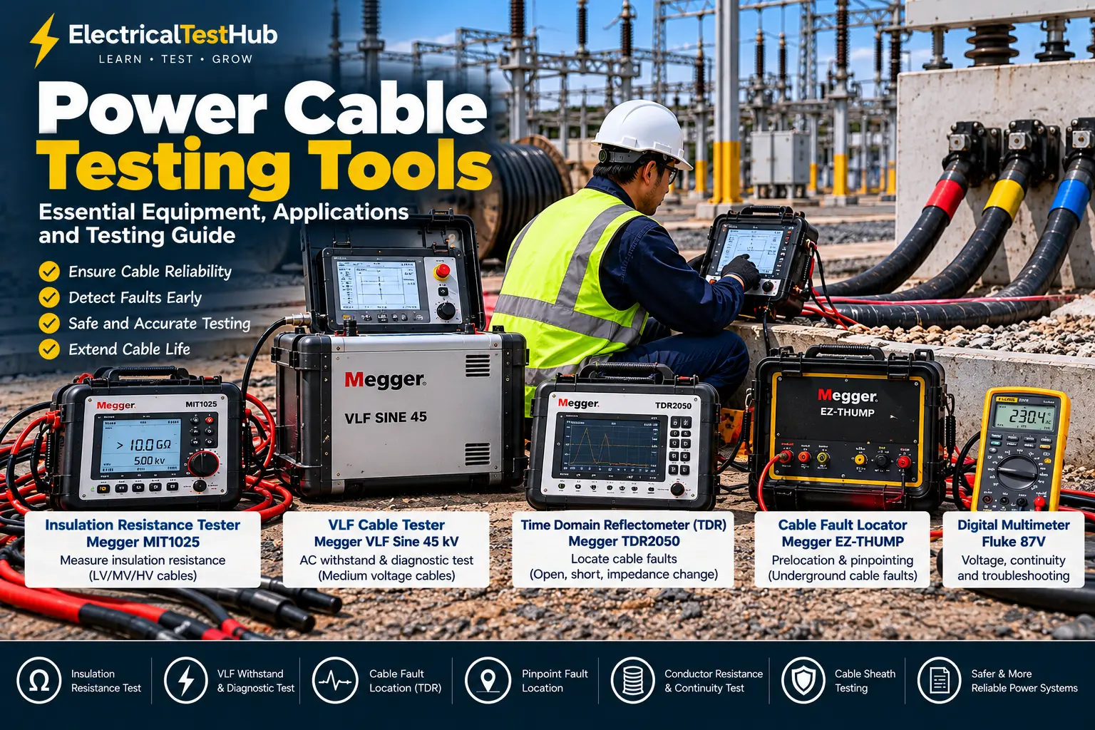
- Megger MIT400/2 Series — insulation and continuity testing instruments for electrical maintenance.
- Fluke 1587 FC Insulation Multimeter — combines insulation resistance testing with multimeter functions.
Important considerations
Select the test voltage according to the cable rating, insulation type, applicable procedure and manufacturer’s instructions. Do not assume that a higher test voltage is always better.
For shielded MV and HV cables, a conventional insulation resistance test does not replace the required acceptance or diagnostic tests.
3. VLF Cable Testing Equipment
Very Low Frequency (VLF) testing equipment is widely used for field testing and diagnostics of shielded medium-voltage power cables.
What is VLF testing?
A VLF tester applies an AC test voltage at a frequency below 1 Hz, commonly 0.1 Hz. It is designed to test suitable cable systems without requiring the same power capacity as a conventional power-frequency AC test set for comparable capacitive loads.
Depending on the instrument and selected procedure, VLF equipment can support:
- AC withstand testing
- Cable insulation diagnostics
- Tan delta measurement
- Some cable sheath testing functions
- Selected partial discharge diagnostic configurations
VLF testing is particularly relevant to shielded medium-voltage cables, including suitable XLPE-insulated cable systems.
Example equipment
Megger VLF Sine 45 kV: A portable cable test system intended for MV cable withstand testing and diagnostics, with optional tan delta functionality.
Official product information: Megger VLF Sine 45 kV.
When is a VLF tester used?
A VLF system may be selected for:
- Acceptance testing of new cable installations
- Maintenance testing of suitable in-service cables
- Evaluating cable insulation condition
- Investigating possible insulation defects
The test voltage, duration, waveform and acceptance criteria must follow the applicable standard, cable manufacturer’s instructions and approved project procedure. An incorrect test can damage cable insulation.
4. Time Domain Reflectometer (TDR)
A Time Domain Reflectometer (TDR) is an important instrument for estimating the location of certain cable faults.
How does a TDR work?
A TDR sends a low-energy electrical pulse into a cable and analyses reflections caused by changes in the cable’s electrical impedance.
The instrument displays a trace showing reflections against time or calculated distance. By using the cable’s propagation velocity, it estimates the distance to a reflection point.
TDRs can help identify:
- Open circuits
- Short circuits
- Impedance changes
- Some cable joint or termination abnormalities
- The approximate location of certain cable faults
Example equipment
The Megger TDR2050 is part of Megger’s cable fault testing range.
Limitations of TDR
A TDR does not identify every fault equally well. High-resistance faults and faults that do not produce a clear impedance change may be difficult to locate using TDR alone.
For some faults, engineers may need additional equipment, such as a surge generator, arc-reflection system or acoustic/electromagnetic pinpointing receiver.
Practical tip: Treat a TDR distance as an estimate, not the exact excavation point. Cable routing, joints, propagation velocity settings and the quality of the trace can affect accuracy.
5. Cable Fault Locator
A cable fault locator is used to identify and locate faults in underground or installed power cable systems.
Why is a cable fault locator needed?
When an underground cable fails, simply knowing that a fault exists is not enough. The maintenance team needs to locate the affected section before opening the ground or carrying out repairs.
Cable fault location normally involves two stages:
- Prelocation: Estimate the distance to the fault using an appropriate method.
- Pinpointing: Narrow down the location on-site using suitable detection techniques.
Common fault location methods
| Method | Typical application |
|---|---|
| TDR | Open circuits and impedance-changing faults |
| Arc reflection | Certain high-resistance faults, with compatible equipment |
| Impulse current method | Selected cable fault location applications |
| Acoustic and electromagnetic pinpointing | Locating the fault point near the ground surface |
| Cable route tracing | Identifying the cable path before excavation |
Example equipment
Megger offers several cable fault location solutions, including portable systems and equipment for more advanced applications.
Explore the official Megger Cable Fault Testing range.
Safety note: Surge generators and high-energy fault location equipment must be operated only by trained personnel using the manufacturer’s approved procedure.
6. Cable Sheath Testing Equipment
Cable sheath testing equipment is used to assess the integrity of a cable’s outer sheath or oversheath.
Why is sheath testing important?
The outer sheath helps protect the cable from moisture, corrosion and mechanical or environmental damage. A damaged sheath may allow moisture ingress or create problems with metallic screens and earthing arrangements.
Sheath testing can be useful after cable installation, jointing, repair or excavation work, when required by the cable design and approved test procedure.
What can sheath testing identify?
- Sheath damage
- Certain insulation defects in the oversheath
- Possible paths for moisture ingress
- Damage associated with installation or repair work
Example equipment
Some VLF cable testing systems also provide sheath testing functions. For example, the Megger VLF Sine 45 kV supports sheath testing with the appropriate configuration.
IEC 60229 is a relevant standard for tests on extruded oversheaths of cables with special protective functions. Always verify that the particular test method applies to the cable construction and installation.
7. Conductor Resistance Tester / Micro-Ohmmeter
A low-resistance ohmmeter or micro-ohmmeter is used to measure low electrical resistance accurately.
Why measure cable conductor resistance?
Conductor resistance measurement can help assess conductor continuity and compare measured resistance with the expected value after accounting for conductor material, cross-sectional area, length and temperature.
It may help identify:
- Incorrect conductor connections
- Abnormal resistance in a cable circuit
- Certain conductor or jointing defects
- Differences between phases that require investigation
Four-wire measurement
A four-wire (Kelvin) method is commonly used for low-resistance measurement because it reduces the influence of test lead resistance on the measured value.
Example equipment
Megger manufactures low-resistance measurement instruments. Select a suitable instrument based on the expected resistance, required test current and measurement accuracy.
Official manufacturer website: Megger.
Important note
For long power cables, conductor resistance can be very low. Ensure that the instrument, connections, temperature correction and measurement procedure are appropriate for the cable under test.
8. Digital Multimeter (DMM)
A digital multimeter is a basic but valuable tool for preliminary checks and troubleshooting.
Common uses
A suitable multimeter can be used for:
- Checking continuity on isolated conductors
- Measuring voltage where the measurement is authorized and safe
- Checking control and auxiliary circuits
- Troubleshooting certain connection problems
Example equipment
The Fluke 87V Digital Multimeter is designed for industrial electrical troubleshooting.
Limitation
A normal multimeter is not a substitute for an insulation resistance tester, a VLF test system or a cable fault locator. Continuity alone does not prove that cable insulation is healthy.
Never use resistance or continuity mode on an energized circuit.
9. Cable Identifier and Phase Identification Equipment
Cable identification equipment helps engineers identify a specific cable among several cables in a trench, cable tray, switchroom or substation.
Where is it used?
- Identifying a cable before maintenance
- Confirming cable route information
- Distinguishing cables in crowded installations
- Supporting phase identification and circuit verification with suitable equipment
Why is this important?
Selecting the wrong cable can result in outages, equipment damage or severe injury. Identification must be performed using a safe, approved method and supported by the required isolation and verification steps.
Important: A cable identifier is not, by itself, proof that a cable is de-energized. Follow the site’s isolation procedure and verify the absence of voltage using an appropriately rated voltage detector.
10. Partial Discharge and Tan Delta Diagnostic Equipment
For important MV and HV cable systems, advanced diagnostic equipment can provide information beyond a simple pass/fail test.
Partial discharge (PD) testing
Partial discharge measurement detects localized electrical discharges that do not completely bridge the insulation between conductors. Depending on the method and test setup, PD diagnostics can help locate or assess insulation defects in cable accessories and cable insulation systems.
Tan delta testing
Tan delta, also called dissipation factor, evaluates dielectric losses in insulation under an applied AC test voltage. It can help assess insulation condition and identify abnormal loss characteristics.
When are these tools used?
- Condition assessment of important MV and HV cable circuits
- Investigating ageing insulation
- Assessing cable systems where a basic insulation resistance test is insufficient
- Supporting maintenance and replacement decisions
These are specialist tests. Results require appropriate experience, measurement setup and interpretation; a single diagnostic value should not automatically be treated as a definitive pass or fail.
Explore Megger’s Cable Testing and Diagnostics range.
11. Comparison of Power Cable Testing Tools
| Testing tool | Main purpose | Typical application |
|---|---|---|
| Insulation resistance tester | Measures insulation resistance | Routine LV checks and appropriate cable tests |
| VLF test set | AC withstand and selected diagnostics | Suitable shielded MV cable systems |
| TDR | Estimates distance to impedance changes | Cable fault prelocation |
| Cable fault locator | Locates and helps pinpoint faults | Underground cable troubleshooting |
| Sheath tester | Checks oversheath integrity | Applicable cable sheath tests |
| Micro-ohmmeter | Measures low resistance | Conductor resistance and selected joint checks |
| Digital multimeter | Basic electrical measurements | Preliminary checks and control circuits |
| Cable identifier | Helps identify a particular cable | Cable identification and maintenance |
| PD diagnostic system | Detects partial discharge activity | Specialist cable condition assessment |
| Tan delta system | Measures dielectric loss | Specialist insulation diagnostics |
The tools listed above are not interchangeable. The correct instrument depends on the cable type, voltage rating, test objective and approved procedure.
12. Basic Power Cable Testing Procedure
The following is a general workflow for trained personnel. The actual procedure must follow the applicable standard, manufacturer’s instructions and site safety rules.
Step 1: Review the cable information
Confirm:
- Cable type and insulation material
- Rated voltage and number of cores
- Conductor size and length
- Cable route and termination details
- Manufacturer’s instructions
- Required commissioning or maintenance tests
Step 2: Isolate the cable
Obtain authorization and isolate the cable from every possible source, including backfeed sources. Apply lockout/tagout and verify the absence of voltage using an appropriately rated detector and approved procedure.
Step 3: Inspect the cable
Check accessible cable sections, terminations, glands, joints and sheath for visible damage, contamination, moisture or installation problems.
Step 4: Perform preliminary checks
Carry out appropriate continuity, conductor identification and insulation resistance checks. Record the test voltage, duration, temperature, connections and readings.
Step 5: Perform specialist tests where required
Depending on the cable and scope, this may include conductor resistance, sheath integrity, VLF withstand, tan delta or partial discharge testing.
Do not apply a high-voltage test simply because the equipment is available. Confirm that the test is suitable for the cable and that the required test voltage and duration have been approved.
Step 6: Discharge and earth the cable
After insulation resistance or high-voltage testing, discharge the cable using the approved equipment and procedure. Cables can retain charge after a test has ended. Apply temporary protective earthing where required and verify safe conditions before touching conductors.
Step 7: Analyse and document the results
Compare readings with applicable acceptance criteria, manufacturer guidance, previous measurements and the project specification. Record any abnormal results for investigation.
Step 8: Restore the system safely
Remove temporary connections and earths only according to the approved switching procedure. Confirm that the cable is correctly terminated, identified and ready for the authorized next step.
For more information about interpreting results, read Understanding Electrical Test Results.
13. Applicable Standards for Power Cable Testing
The relevant standard depends on cable construction, voltage rating, test type and whether the cable is being tested in a factory or in the field.
| Standard | Main relevance | Official reference |
|---|---|---|
| IEC 60502-1 | Power cables with extruded insulation for rated voltages from 1 kV up to 3 kV | IEC Webstore |
| IEC 60502-2 | Power cables with extruded insulation rated from 6 kV up to 30 kV | IEC 60502-2 |
| IEEE 400-2023 | Field testing and evaluation of shielded power cable system insulation rated 5 kV and above | IEEE 400-2023 |
| IEEE 400.2-2024 | Field testing of shielded power cable systems using VLF below 1 Hz | IEEE 400.2-2024 |
| IEC 60229 | Tests on extruded oversheaths of cables with special protective functions | IEC Webstore |
IEC 60502-2 specifies construction, dimensions and test requirements for applicable extruded-insulation power cables rated from 6 kV to 30 kV. IEEE 400.2-2024 addresses VLF field testing of shielded cable systems. See the official IEC publication and IEEE guide.
Always confirm the current edition and relevant clauses before preparing a formal test procedure or report. Do not treat one standard as a universal source of acceptance limits for every cable test.
14. Essential Safety Precautions
Power cable testing can involve hazardous stored energy and high test voltages. Follow the approved risk assessment and safety procedure.
- Only trained and authorized personnel should perform cable testing.
- Isolate all sources and apply lockout/tagout.
- Verify the absence of voltage before connecting test equipment.
- Confirm the correct cable and test points before starting.
- Use correctly rated, inspected test leads and accessories.
- Establish barriers and warning signs around high-voltage test areas.
- Keep personnel clear while a high-voltage test is in progress.
- Discharge and earth the cable after testing as specified by the procedure.
- Never disconnect test leads while the cable is energized or still charged.
- Do not apply a DC withstand test to an installed cable system without confirming that the method is suitable for its insulation type and condition.
For general background, see our guide to Why Electrical Testing Is Important.
15. How to Select the Right Cable Testing Equipment
Before purchasing or selecting a test instrument, consider the following:
1. Cable voltage rating: An LV insulation tester is not a replacement for a dedicated MV cable test system.
2. Cable insulation: XLPE, PVC, PILC and other constructions can require different test methods and limits.
3. Test purpose: Routine insulation checks, acceptance testing, condition assessment and fault location require different tools.
4. Cable length and capacitance: VLF and other high-voltage systems have limits on testable cable capacitance and may need to adjust frequency or configuration.
5. Required standards: Check the project’s specified standards and the instrument manufacturer’s instructions.
6. Reporting requirements: Choose equipment that can record the measurements and test conditions required for a traceable report.
7. Calibration and support: Confirm instrument calibration status, accessories, training and technical support.
Frequently Asked Questions (FAQ)
1. Which instrument is used for power cable testing?
The instrument depends on the test. An insulation resistance tester is commonly used for insulation checks, a VLF test set for suitable MV cable withstand testing, and a TDR or cable fault locator for fault location.
2. Can a Megger detect all cable faults?
No. An insulation resistance tester can identify certain insulation problems, but it cannot locate every fault or fully assess cable condition. Other methods may be needed.
3. What is the difference between a Megger and a VLF tester?
A Megger typically measures insulation resistance using DC. A VLF tester applies low-frequency AC voltage for specified withstand or diagnostic tests on suitable cable systems. They serve different purposes.
4. What is a TDR used for in cable testing?
A TDR analyses reflections from electrical impedance changes to estimate the distance to a cable fault or other discontinuity.
5. Is VLF testing necessary for every cable?
No. VLF testing is used for appropriate cable systems and test objectives. The required test depends on the cable design, voltage rating, project specification, applicable standard and manufacturer’s recommendations.
6. Can I use a normal multimeter to test cable insulation?
A normal multimeter can check continuity and perform other basic measurements, but it cannot replace an insulation resistance tester or high-voltage cable test equipment.
7. Which standard is relevant to MV power cable testing?
IEC 60502-2 is relevant to the construction and test requirements of applicable extruded-insulation cables rated from 6 kV to 30 kV. IEEE 400 and IEEE 400.2 address field testing and evaluation of shielded power cable systems. The applicable requirements depend on the specific test and project.
Conclusion
Selecting the right power cable testing tools is essential for safe commissioning, reliable maintenance and effective troubleshooting. An insulation resistance tester is useful for appropriate routine checks, while VLF systems, TDRs, sheath testers and advanced diagnostic instruments serve more specialized purposes.
Electrical engineers should select instruments based on cable construction, voltage rating, test objective and applicable standards. Equally important are safe isolation, correct test connections, proper discharge and accurate reporting.
Understanding each tool’s capabilities and limitations helps technicians carry out more reliable cable testing and make better maintenance decisions.
Disclaimer: This article is for educational purposes. Actual cable testing must be performed by qualified personnel using approved procedures, applicable standards and the instrument manufacturer’s instructions.
