

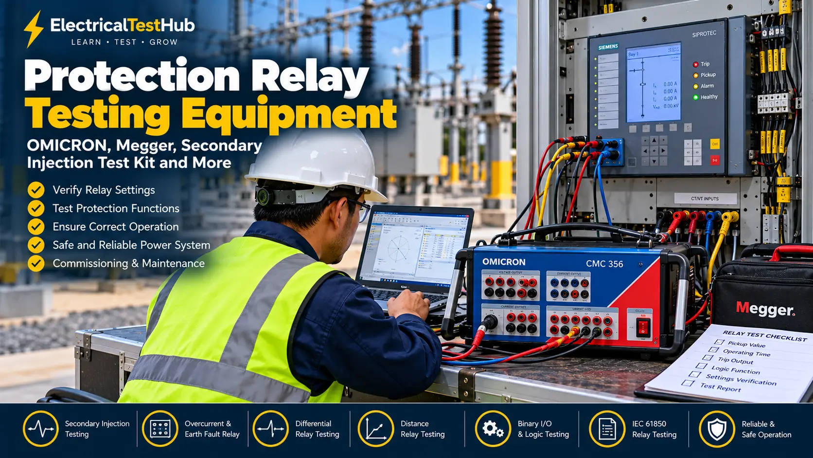
Introduction
Protection relays are essential components of electrical power systems. They continuously monitor electrical quantities such as current, voltage, frequency and impedance. When a fault or abnormal operating condition occurs, the protection relay sends a trip command to the circuit breaker to isolate the affected section.
However, installing a protection relay does not automatically guarantee that it will operate correctly. The relay’s settings, input connections, protection logic, trip output and communication functions must be tested and verified.
Protection relay testing equipment helps electrical engineers and commissioning technicians confirm that a relay operates according to its approved settings and protection philosophy.
In substations, industrial plants, power stations and distribution networks, relay testing is commonly performed during commissioning, preventive maintenance, troubleshooting and protection system modifications.
This guide explains the main protection relay testing tools, their applications, practical testing methods, manufacturer examples, relevant standards and safety precautions.
1. What Is Protection Relay Testing Equipment?
Protection relay testing equipment consists of instruments used to inject electrical signals into a relay and verify its response.
Depending on the relay and test objective, the equipment may generate controlled current, voltage, frequency, phase angle and simulated fault conditions.
Typical applications include:
- Overcurrent and earth-fault relay testing
- Overvoltage and undervoltage relay testing
- Differential protection testing
- Distance protection testing
- Frequency and rate-of-change-of-frequency protection testing
- Directional protection testing
- Circuit breaker trip circuit verification
- Relay logic, binary input and output testing
- IEC 61850 GOOSE and Sampled Values testing, where supported
Relay testing equipment can range from a simple secondary injection kit to a sophisticated computerized protection relay test system.
For a broader introduction, read our guide to Types of Electrical Testing.
2. Secondary Injection Relay Test Kit
Image placement: Insert a photograph of an OMICRON or Megger secondary injection relay test kit connected to a numerical protection relay.
A secondary injection test kit is one of the most widely used tools for testing protection relays.
How does secondary injection work?
A secondary injection test set supplies controlled current and voltage signals directly to the relay’s secondary input circuits. The engineer then checks whether the relay responds correctly to the injected values.
For example, when testing an overcurrent relay, the test set can gradually increase the injected current to determine the pickup value and measure the operating time.
What can it test?
- Relay pickup and dropout values
- Operating time
- Current and voltage measurement
- Phase-angle response
- Directional characteristics
- Protection logic and selected binary inputs and outputs
- Trip contact operation
The exact capabilities depend on the test set and the relay function.
Example equipment
OMICRON CMC series: OMICRON provides computerized relay test systems for testing different types and generations of protection relays.
Official manufacturer reference: OMICRON CMC 356.
Megger SMRT and FREJA series: These test systems support protection relay testing, with capabilities depending on the model and configuration.
Official manufacturer reference: Megger Relay Test Management Software.
Practical example
Suppose an overcurrent relay has a configured pickup setting of 1 A secondary.
The engineer injects a current according to the approved test plan and checks the relay’s pickup response. The measured pickup and operating time are then compared with the approved settings and the manufacturer’s specified tolerances.
The actual test current and expected operating time must be calculated from the relay configuration and its time-current characteristic. There is no single test value suitable for every overcurrent relay.
3. OMICRON Protection Relay Test Equipment
Image placement: Insert a clear photograph of an OMICRON CMC relay test set connected to a protection relay and laptop.
OMICRON is a well-known manufacturer of test equipment for protection relays, power system components and substation commissioning.
OMICRON CMC 356
The CMC 356 is a universal relay test set with six current sources and capabilities for testing many types of protection relays. It can also support selected wiring and plausibility checks involving current transformers.
The CMC 356 has been succeeded by the CMC 500 in OMICRON’s product portfolio, so users planning a new purchase should check the manufacturer’s current product and support information.
Official links:
What can OMICRON relay testing equipment do?
Depending on the test set, software and relay, it can support:
- Overcurrent and earth-fault testing
- Distance protection testing
- Differential protection testing
- Voltage and frequency protection testing
- Binary input and output checks
- Automatic test sequences
- Fault simulation and report generation
- Selected IEC 61850-based tests with compatible options
Why do engineers use computerized relay test systems?
A computerized test system can generate repeatable test signals, execute predefined test sequences and document measured results. This is useful when multiple relays need to be tested during a substation commissioning project.
The test system does not automatically determine whether every protection scheme is correctly designed. Engineers must verify the approved settings, CT/VT ratios, logic, wiring diagrams and protection philosophy.
4. Megger Relay Testing Equipment
Image placement: Insert a photograph of a Megger SMRT or FREJA relay test system used for secondary injection testing.
Megger manufactures relay testing systems and software for protection testing, commissioning and maintenance.
Megger SMRT series
SMRT relay test systems are designed for testing protection relays and related protection functions. Available current and voltage outputs, binary channels and testing features vary by model.
Megger FREJA series
FREJA systems support relay testing applications, including automatic test sequences and tests for supported protection functions.
Megger RTMS software
Megger’s Relay Test Management Software (RTMS) supports manual, semi-automatic and automatic testing with compatible Megger test systems. Features vary by software level and test equipment.
Official manufacturer link:
Explore Megger RTMS Relay Test Management Software
When should you choose OMICRON or Megger?
The choice depends on the relay types in use, required test functions, available accessories, software compatibility, report requirements, training and service support.
Rather than selecting equipment only by brand, prepare a technical specification based on the protection functions and tests your organization performs.
5. Primary Injection Test Equipment
Image placement: Insert a photograph of a high-current primary injection test set connected to a circuit breaker or current transformer primary circuit.
Primary injection testing differs from secondary injection testing because the test current is injected into the primary current path rather than directly into the relay’s secondary current inputs.
What is primary injection testing?
A primary injection test set generates a high current that passes through the primary circuit, such as a busbar, circuit breaker or current transformer primary conductor.
Depending on the test arrangement, this can help verify aspects of the complete current path, including CT response and the associated secondary measurement circuit.
Common applications
- Current transformer ratio and polarity-related checks within the approved test scope
- Circuit breaker primary current path checks
- Verification of CT secondary circuit response
- Selected protection scheme checks
Example equipment
Primary injection systems are available from several manufacturers, including Megger and other specialist electrical test equipment suppliers.
Official manufacturer website: Megger.
Primary injection vs. secondary injection
| Item | Primary injection | Secondary injection |
|---|---|---|
| Injection point | Primary current path | Relay secondary inputs |
| Typical current level | High current | Relay-level current and voltage |
| Main focus | Primary path and selected CT-related checks | Relay measurement and protection response |
| Test equipment | High-current injection set | Relay test set |
| Main limitation | May require significant current and suitable primary connections | Does not by itself verify the entire primary current path |
These methods are complementary. Secondary injection alone does not prove that every CT primary connection, CT ratio, wiring connection and trip circuit is correct.
6. Digital Multimeter for Relay Testing
Image placement: Insert a photograph of a Fluke 87V industrial digital multimeter used for control circuit checks.
A digital multimeter is a useful supporting instrument during relay commissioning and troubleshooting.
Common applications
- Checking control circuit voltage
- Verifying continuity on isolated circuits
- Checking relay auxiliary supply
- Checking selected trip circuit connections
- Troubleshooting binary input wiring
Example equipment
The Fluke 87V Digital Multimeter is designed for industrial electrical troubleshooting.
Important limitation
A multimeter cannot replace a relay test set. It may verify a voltage or continuity condition, but it cannot independently confirm a relay’s operating curve, pickup accuracy, directional characteristic or differential protection performance.
Never use continuity or resistance mode on an energized circuit.
7. Timer and Trip Circuit Testing Tools
Image placement: Insert a photograph showing a protection relay trip output connected to a timer or binary input of a relay test set.
Operating time is a critical measurement when testing many protection functions.
For an overcurrent relay, the operating time may depend on the injected current and the configured time-current characteristic.
What is checked?
- Time from the start of the test signal to relay pickup
- Time from the start of the test signal to relay trip contact operation
- Operation of the trip output
- Selected interlocks and breaker trip logic
- Breaker auxiliary contacts, where included in the approved test scope
Many modern relay test systems include binary inputs that can record contact transitions and measure operating time. A separate timer may be useful for specific tests or independent verification.
Practical example
An inverse-time overcurrent relay should operate faster at a higher multiple of pickup current, subject to the configured curve and operating range.
The engineer injects the specified test currents, measures the relay operating times and compares the results with the expected values calculated from the approved curve.
Do not use a generic operating time as a universal acceptance criterion. The expected time depends on the relay settings and the selected test point.
8. Protection Relay Testing Software
Image placement: Insert a screenshot or photograph of relay testing software displaying current, voltage, a test sequence and measured operating times.
Relay testing software helps engineers prepare test plans, control compatible test equipment, evaluate results and generate reports.
Common functions
- Manual injection control
- Automatic pickup and timing tests
- Fault simulation
- Distance relay characteristic testing
- Differential relay testing
- Test sequence management
- Results evaluation and reporting
- Supported IEC 61850 testing functions
Examples
OMICRON Test Universe: A software environment used with compatible OMICRON test equipment for protection relay testing.
Official website: OMICRON.
Megger RTMS: Software for compatible Megger SMRT and FREJA relay test systems.
Official product link: Megger RTMS.
Software capability depends on the connected test set, licenses, available modules and the relay being tested.
9. IEC 61850 Testing Tools
Image placement: Insert a photograph of a protection relay test setup with a laptop, network switch and IEC 61850-compatible test equipment.
Modern digital substations may use IEC 61850 communication for protection, control and monitoring.
In these systems, some protection functions receive digital current and voltage information through Sampled Values streams, exchange status or control messages using GOOSE, or rely on time synchronization messages.
What equipment may be required?
Depending on the substation architecture, engineers may need:
- Compatible relay test equipment
- IEC 61850 test software
- GOOSE monitoring and simulation tools
- Sampled Values analysis tools
- Suitable Ethernet interfaces and network equipment
- Access to approved configuration files and system documentation
What can be tested?
- GOOSE publish/subscribe behaviour
- Binary status and trip message handling
- Sampled Values input processing
- Communication-related protection logic
- Selected timing and synchronization functions
IEC 61850 testing requires a clear understanding of the system configuration. An ordinary secondary injection test does not necessarily validate the complete digital communication path.
For standards information, consult the IEC Webstore.
10. Common Protection Relay Tests
| Protection function | Typical test | What is verified? |
|---|---|---|
| Overcurrent (50/51) | Pickup and timing | Pickup threshold and operating curve |
| Earth fault (50N/51N) | Current injection and timing | Earth-fault pickup and operating response |
| Over/undervoltage (59/27) | Voltage injection | Pickup, dropout and timing |
| Frequency (81) | Frequency variation | Frequency threshold and time response |
| Differential (87) | Multiple current inputs and phase relationships | Differential operate and restraint characteristics |
| Distance (21) | Impedance and fault simulation | Reach, directional response and operating zones |
| Directional overcurrent (67) | Current and voltage with controlled phase angle | Directional decision and pickup |
| Breaker failure (50BF) | Logic and timing simulation | Initiation, timing and output logic |
| Synchronism check (25) | Voltage magnitude, phase angle and frequency simulation | Permissive conditions and blocking behaviour |
Not every relay test set supports every test automatically. Some functions require specific software modules, extra channels, communication interfaces or a defined test configuration.
11. Basic Protection Relay Testing Procedure
The following is a general workflow for trained electrical testing personnel. Always follow the relay manufacturer’s instructions, approved settings, site safety rules and project-specific test procedure.
Step 1: Review the protection documents
Collect and verify:
- Approved relay setting file
- Protection coordination study, where applicable
- Single-line diagram
- Control and protection wiring diagrams
- CT and VT ratios
- Relay model and firmware information
- Previous test reports, where available
Step 2: Prepare the relay test equipment
Check the test set, leads, connectors, auxiliary supply, calibration status and software configuration. Confirm that the test equipment can provide the required current, voltage and timing measurements.
Step 3: Make the system safe
Obtain authorization and follow the approved isolation and permit-to-work procedure. Identify possible trip paths and unintended breaker operations. Use approved test switches or isolation links as required by the site procedure.
Prevent accidental trips, breaker closure or unintended operation of other equipment. Never disconnect an energized CT secondary circuit.
Step 4: Verify relay settings
Confirm the active settings group, pickup values, time dial or time multiplier, curve type, directional settings, logic and output mapping against the approved configuration.
Step 5: Perform pickup tests
Inject the required current or voltage and determine the point at which the relay operates. Record the measured value and compare it with the approved settings and applicable tolerance.
Step 6: Perform operating time tests
Apply the specified test values and measure the relay operating time. Compare the result with the expected time for that function and test point.
Step 7: Check logic and trip outputs
Verify the relevant binary inputs, output contacts, interlocks and trip logic within the approved test scope. Confirm the actual trip circuit and breaker operation only when explicitly included in the test plan and safely authorized.
Step 8: Test additional functions
For applicable relays, perform directional, differential, distance, frequency or IEC 61850 tests according to the approved procedure.
Step 9: Restore and document
Restore all test switches, links, wiring and settings to the approved service condition. Independently verify the final status before returning the protection scheme to service.
Record the test equipment details, settings, injected values, measured pickup values, operating times, observations and final status.
For more information on interpreting measurements, read Understanding Electrical Test Results.
12. Applicable Standards for Protection Relay Testing
The applicable standard depends on the relay function and the test objective. The following are useful starting points.
| Standard | Scope | Official reference |
|---|---|---|
| IEC 60255-1:2022 | Common requirements for measuring relays and protection equipment | IEC 60255-1 |
| IEC 60255-26:2023 | Electromagnetic compatibility requirements | IEC 60255-26 |
| IEC 60255-121:2014 | Functional requirements for distance protection | IEC 60255-121 |
| IEC 60255-181:2019 | Functional requirements for frequency protection | IEC 60255-181 |
| IEC 60255-187-1:2021 | Differential protection for motors, generators and transformers | IEC 60255-187-1 |
These standards cover different aspects of relay requirements and functions; they are not interchangeable. Some address product or functional requirements rather than providing a universal field commissioning checklist.
For actual commissioning or maintenance, follow the applicable project specification, manufacturer procedure, approved relay settings and relevant utility requirements. Confirm the current edition and applicable clauses before referencing a standard in a formal report.
13. Safety Precautions During Relay Testing
Protection relay testing can cause unexpected breaker trips, hazardous voltages or damage to connected equipment if performed incorrectly.
- Only trained and authorized personnel should conduct relay testing.
- Review the approved test plan and protection settings before injection.
- Identify and control all possible trip paths and unintended operations.
- Use approved test switches, isolation links and test connections.
- Never open-circuit an energized CT secondary circuit.
- Confirm the correct relay terminals and current/voltage input ratings.
- Avoid applying current or voltage beyond the relay and test equipment ratings.
- Follow the approved procedure for disabling and restoring protection functions.
- Verify all wiring and settings before returning the relay to service.
- Record any temporary bypasses and confirm their removal before handover.
14. How to Select Protection Relay Testing Equipment
Before purchasing or selecting a relay test set, consider these points:
1. Protection functions: Confirm whether you need overcurrent, differential, distance, directional, frequency or other protection testing.
2. Current and voltage outputs: Check the number of channels, output range, power capability and phase-angle control.
3. Binary inputs and outputs: Ensure the test set can monitor the contact transitions and timing required for your work.
4. Automation and software: Consider automatic test sequences, relay libraries, reporting and support for your relay models.
5. IEC 61850 requirements: For digital substations, check whether GOOSE, Sampled Values and related functions are required.
6. Portability and accessories: Consider the test set’s weight, transport case, lead sets, adapters and field usability.
7. Calibration and support: Verify calibration services, technical training, software updates and local manufacturer support.
8. Future requirements: Select a system that suits the range of protection relays your team is expected to test, not only the current project.
Frequently Asked Questions (FAQ)
1. Which equipment is used for protection relay testing?
Common equipment includes secondary injection relay test sets, primary injection test sets for selected system checks, digital multimeters, timing measurement facilities and compatible relay testing software.
2. What is the difference between primary and secondary injection testing?
Primary injection sends test current through the primary current path, while secondary injection sends controlled current or voltage directly to the relay’s secondary inputs. The two methods verify different parts of the protection system.
3. Which is better: OMICRON or Megger?
Both manufacturers offer protection relay testing equipment. The best choice depends on the relay functions, output requirements, automation, software, accessories, budget and technical support required by your organization.
4. Can a multimeter test a protection relay completely?
No. A multimeter is useful for selected voltage and continuity checks but cannot independently verify all relay pickup values, operating times, curves, directional characteristics or differential functions.
5. What is a secondary injection test kit?
It is a test instrument that injects controlled current and voltage signals into a relay’s secondary input circuits to verify the relay’s measurement and protection response.
6. How often should protection relays be tested?
The interval depends on the equipment manufacturer’s recommendations, criticality of the circuit, operating environment, utility requirements, maintenance strategy and previous test results. Follow the approved maintenance program rather than assuming one interval suits every relay.
7. Which IEC standard applies to protection relay testing?
IEC 60255-1 provides common requirements for measuring relays and protection equipment. Other parts of the IEC 60255 series address specific functions, such as distance, frequency and differential protection. The applicable standard depends on the relay and the test being performed.
Conclusion
Protection relay testing equipment is essential for verifying the performance of electrical protection systems. Secondary injection test sets, primary injection equipment, multimeters, timing facilities and compatible software each serve different purposes.
OMICRON and Megger provide established solutions for protection relay testing, but the right equipment should be selected according to the required protection functions, test scope and technical specifications.
Reliable relay testing requires more than injecting current and voltage. Engineers must verify the approved settings, wiring, protection logic, trip outputs and restoration of the system. Proper documentation and safe working practices help ensure that protection relays are ready for service.
Disclaimer: This article is for educational purposes. Actual protection relay testing must be performed by qualified personnel following approved settings, manufacturer instructions, applicable standards and site safety procedures.
